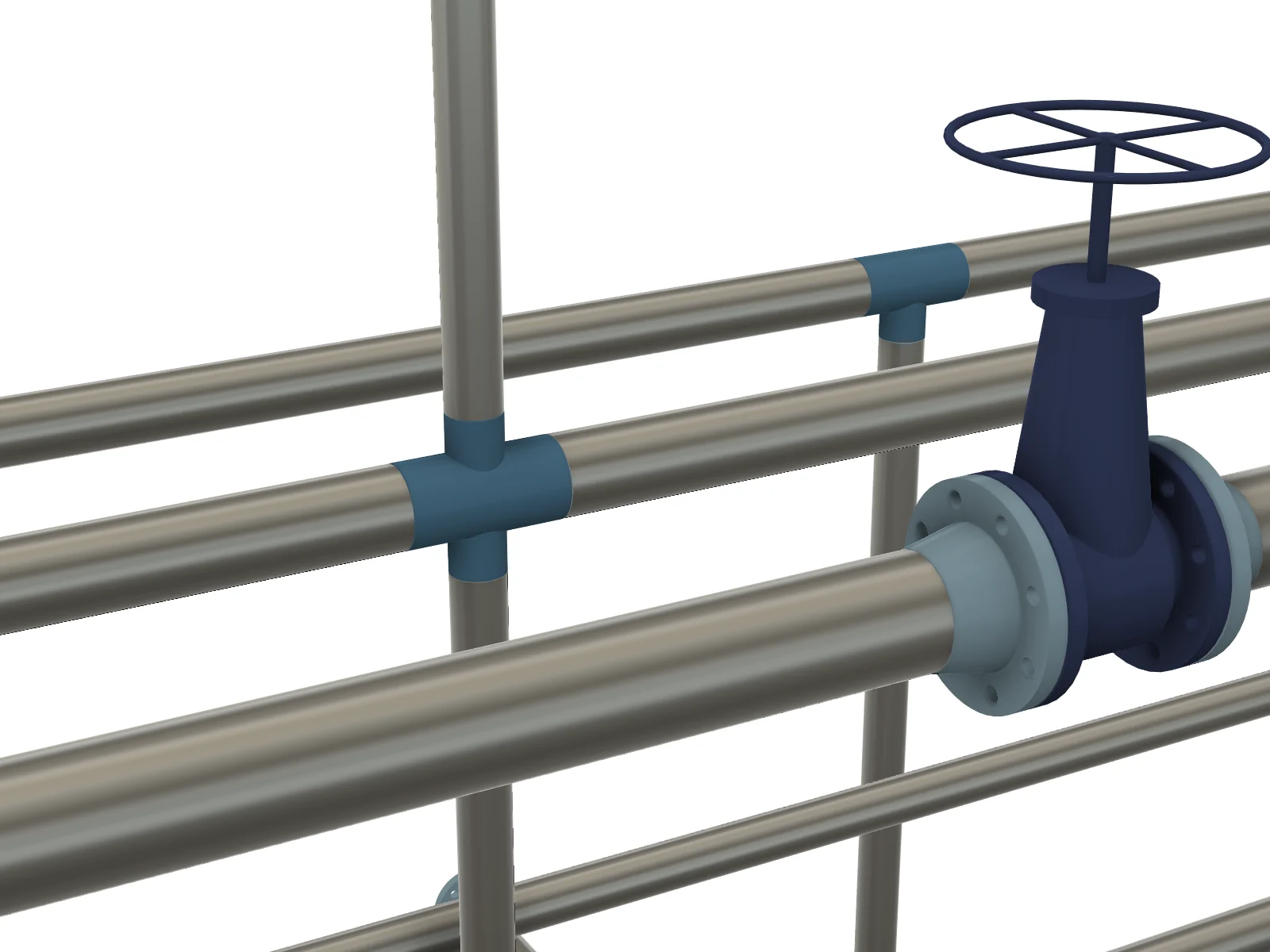
Sizes change at the fittings
A reducing cross takes DN50 branches up and down from the DN80 header, and the DN100 gate valve sits between its mating flanges. Every tube is cut back to the fittings it meets.
Create pipework. Plan tube bends.
Prepare fabrication data in Fusion.
Create and edit tubes from sketch paths. Choose pipe sizes, set bend radii, and add fittings, valves and supports. Use the same model for bend tables, cutting lists, notch templates, weld estimates and fabrication files.
851 stock sizes
44 pipe and tube families
Routes & connections
Editable tubes, fittings and supports
Fabrication data
Bend tables, cut lists and shop files
Video
Switching CAD or routing by hand
Native Autodesk Fusion has Pipe and Sweep for single bodies, and standalone tube-bending data exporters only read an already-modeled tube. Tube & Pipe Routing covers the complete workflow inside Fusion: routing process pipework and bent hydraulic, pneumatic or structural tubes from sketches or XYZ / LRA (YBC) tables, placing fittings, valves and supports with automatic trim-back, and exporting bender setup sheets, notch templates and cut lists.
| Piping / Tube Bending Need | Native Fusion or standalone exporters | Tube & Pipe Routing Add-in |
|---|---|---|
| Pipe & tube stock library | Type OD and wall thickness on every Pipe command | 851 sizes across 44 EN, ASME/ANSI, DIN, ISO, JIS, copper, sanitary & pneumatic families |
| Tees, elbows, reducers, flanges & valves | Import, align by joints and split/trim every pipe end manually | 20 built-in fitting & valve types + Fitting from Model; pipes trim back automatically with takeout and weld gap |
| Rotary draw / CNC tube bender tables (LRA / YBC / XYZ) | Measure straight lengths, bend angles and plane rotations by hand, or use an exporter-only plugin on a single body | Bend Data & Bender Setup: LRA / YBC and XYZ tables, springback compensation, plus Recognize Tube for imported STEP tubes |
| Fishmouth / saddle notch templates | Unfold sheet-metal workarounds or project curves manually | 1:1 printable PDF and flat DXF wrap-around templates for End A / End B pipe-to-pipe copes |
| Pipe clamps, U-bolts & shoes | Model or place each clamp without route association | Pipe Support (split clamps, DIN 3570 / MSS U-bolts, DIN 3015 block clamps, shoes) that follow route edits |
A complete project in Fusion
Three headers on the upper level and a DN50 loop below feed nine drops to the equipment. Each drop has an elbow, a valve between mating flanges and a weld-neck flange; a reducer, reducing tees and a reducing cross join the sizes, and three hydraulic tubes are bent in front of the rack.
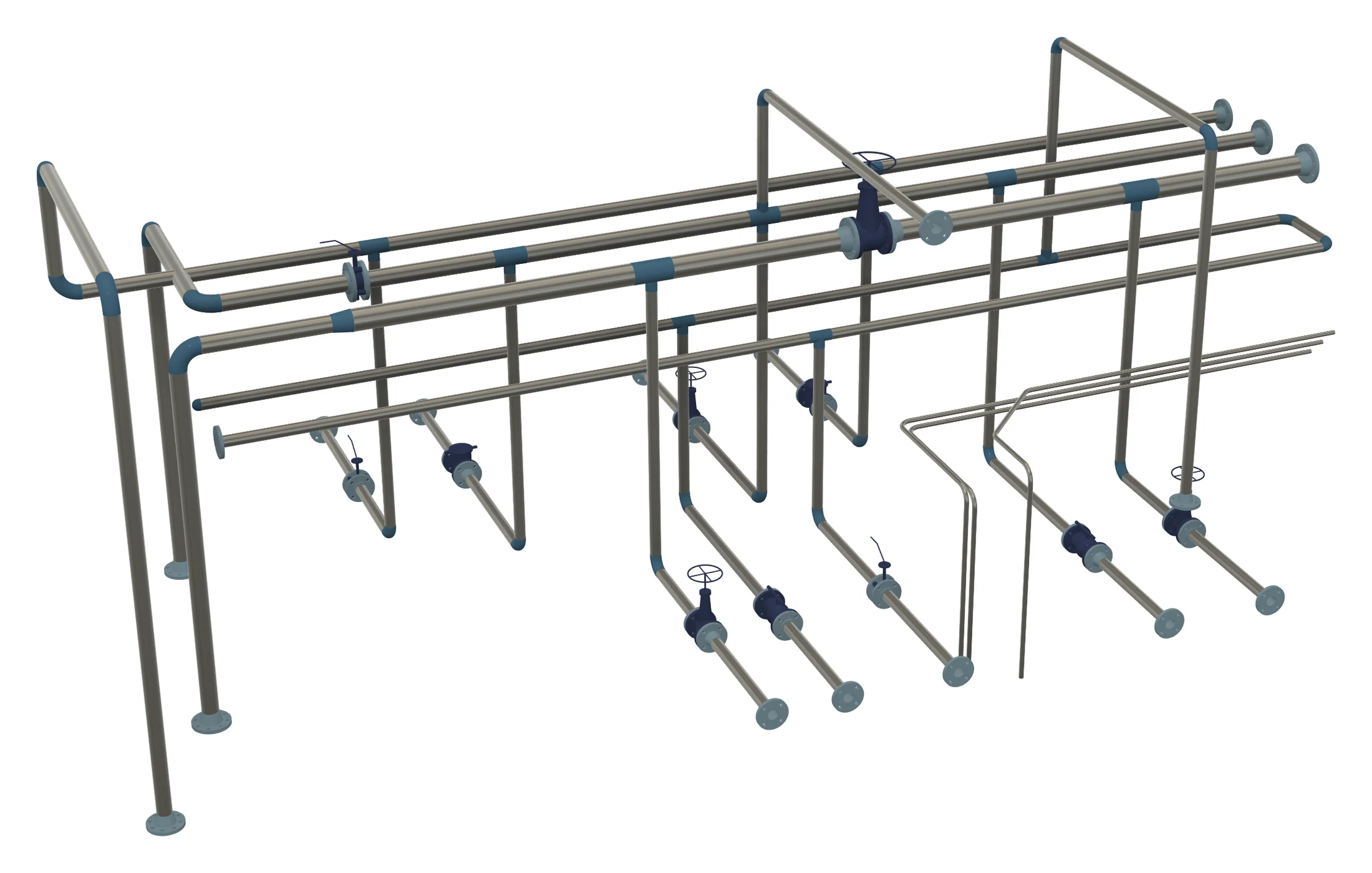
Every route, fitting and valve in this model was created with Tube & Pipe Routing from one sketch of centrelines; nothing was modeled by hand.
A reducing cross takes DN50 branches up and down from the DN80 header, and the DN100 gate valve sits between its mating flanges. Every tube is cut back to the fittings it meets.
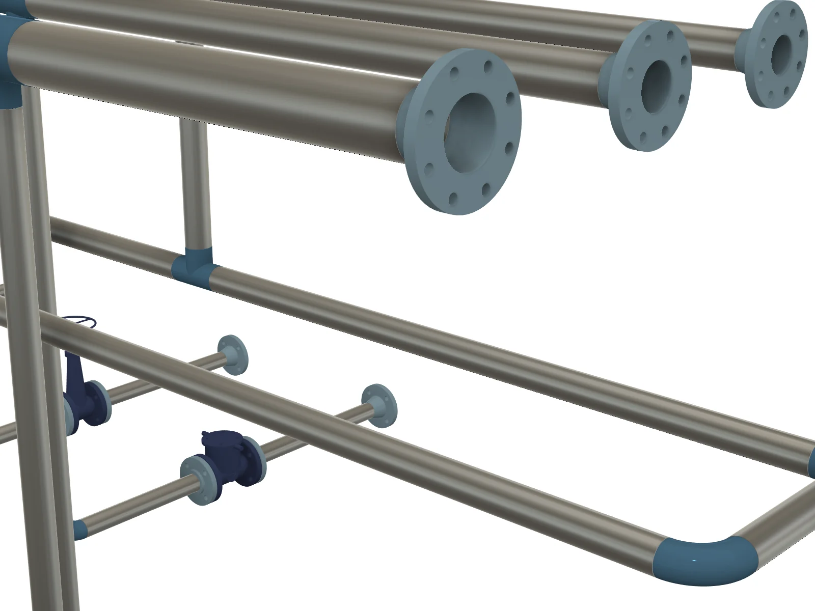
Weld-neck flanges close the header ends, long-radius elbows turn the DN50 loop, and each drop carries its own valve to the equipment flange.
Routes and fittings
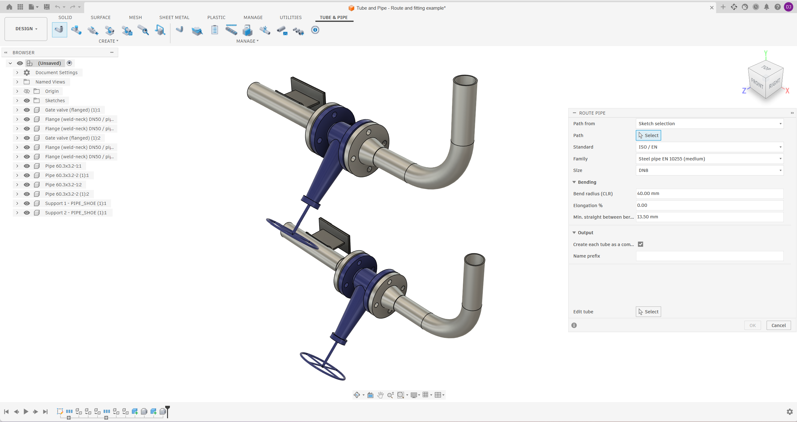
Select connected sketch lines and arcs, choose an outside diameter and wall, and set the centreline bend radius. Separate chains become separate tubes; junctions provide the nodes for fittings.
Load a CSV or paste numeric rows. Select mm or inches and the rotation convention. The result includes an editable source sketch.
Connected pipes trim to the fitting faces, so the layout and cut lengths stay together when you edit.
Capture a solid valve or coupling with circular ports and insertion depths using Fitting from Model. Reuse it where its port directions match the layout.
Auto Route
Choose two points and the obstacles to avoid. Auto Route proposes an orthogonal sketch path with clearance and room for bends; it can build the tube immediately.
The search uses obstacle bounding boxes. The finished tube receives a geometry interference check, so review the result before committing to the layout.
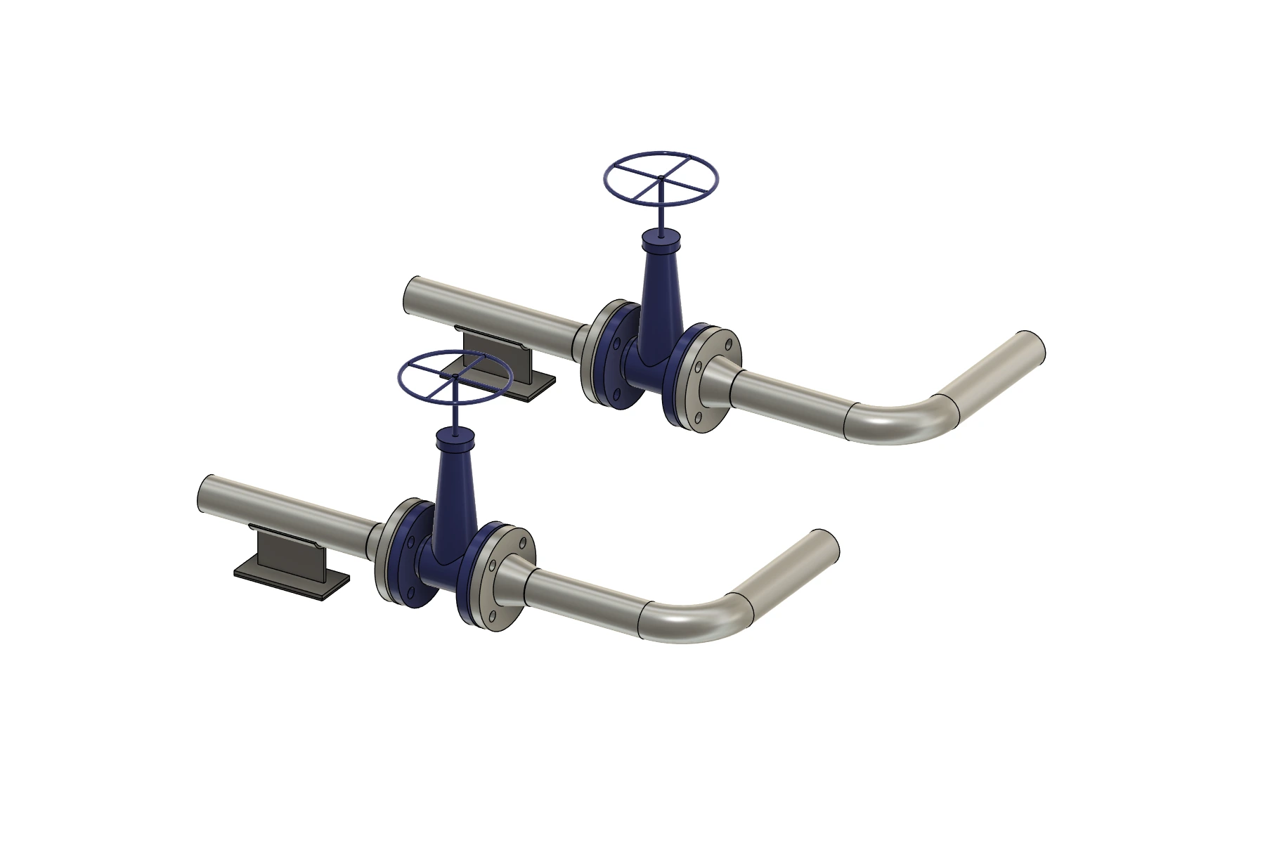
Reopen a route to change its stock size, path or bend radius. These two copies keep their placements and pipe shoes when the bend radius changes from 100 to 180 mm. Rotating the valve by 45° updates its linked pipe flanges too.
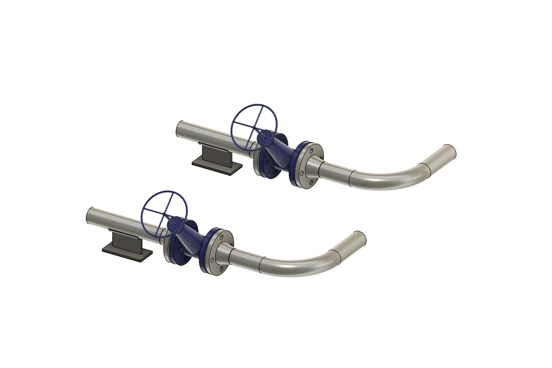
Shown with independent component copies. Nested repeated parents also keep their placements, and linked fittings and support anchors follow the matching pipe instances. Native pattern or mirror seeds, joints, rigid groups and separately moved pieces that cannot be replaced safely are reported before replacement and kept intact.
A closer look at the connections
Branch a line, change diameter, turn a corner or fit a valve. These examples were created in Fusion with the add-in.
Fitting
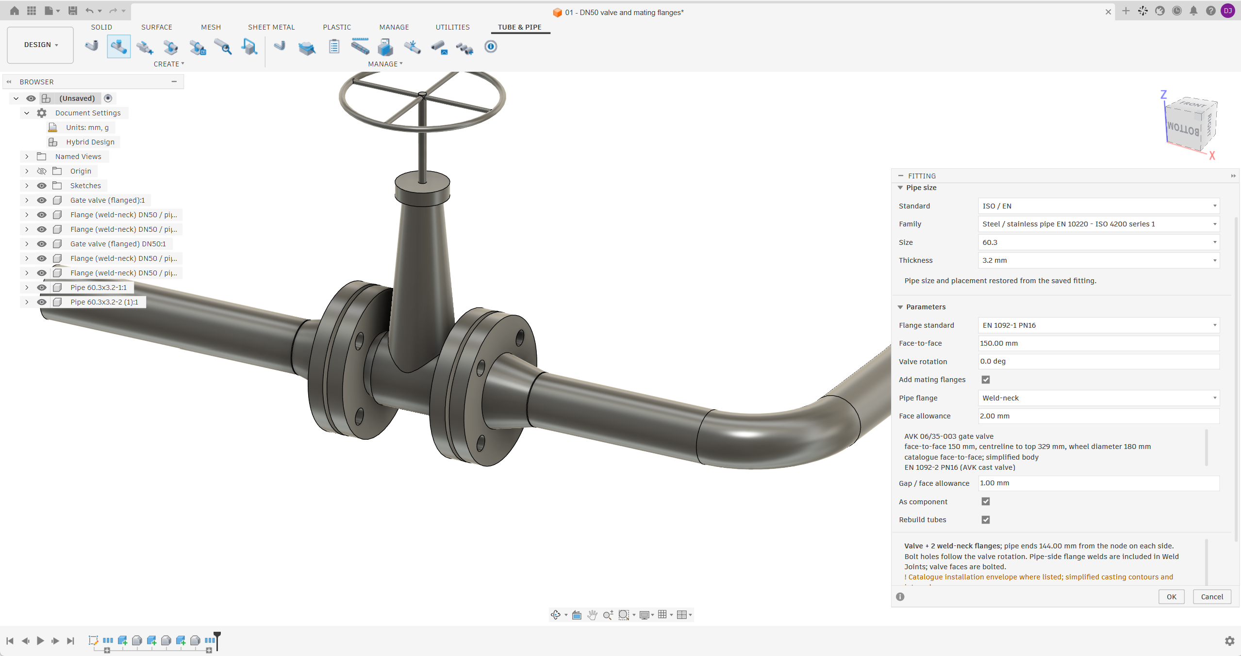
Enable Add mating flanges for a supported built-in flanged or wafer valve. Choose slip-on or weld-neck flanges and set the face (gasket) allowance and the pipe-end setback or root gap. The command checks the connection dimensions, aligns the bolt patterns and trims the pipes. Edit any of the three parts to update the set; the BOM counts them separately.
Bolts and gaskets are not modeled.
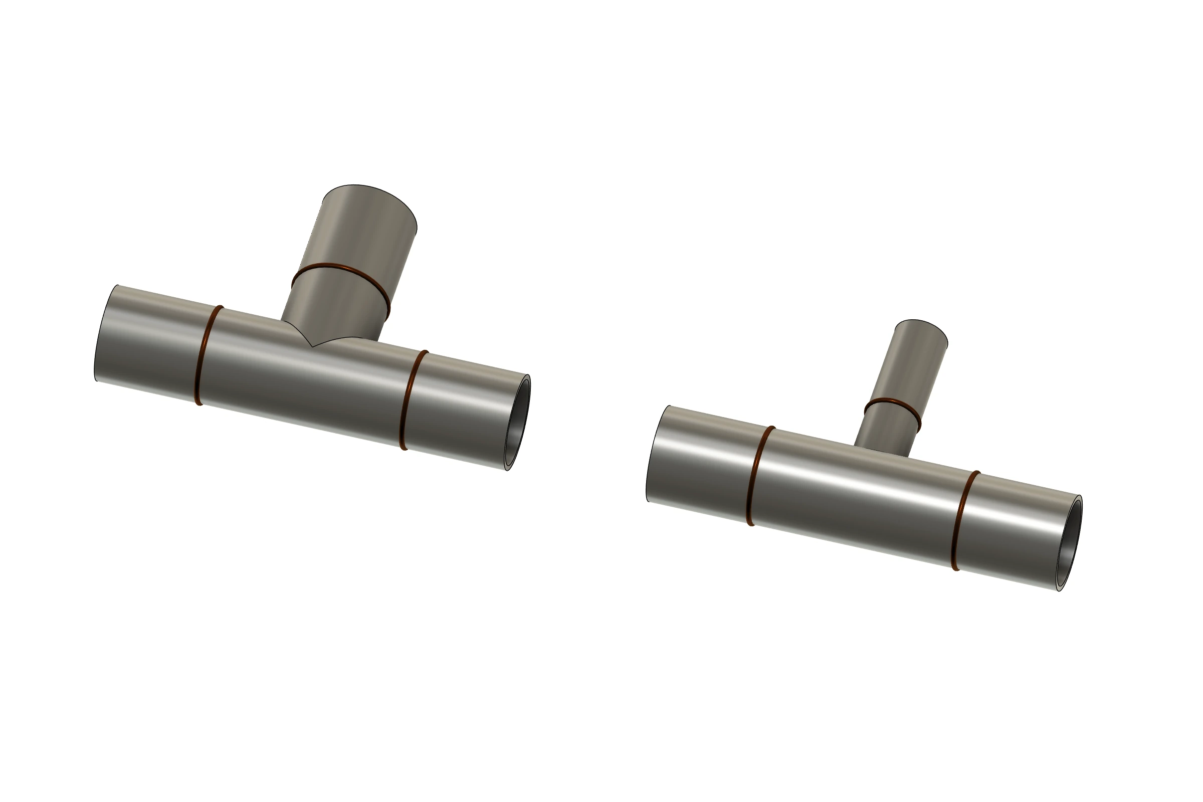
Add a branch with the same bore or a smaller outlet.
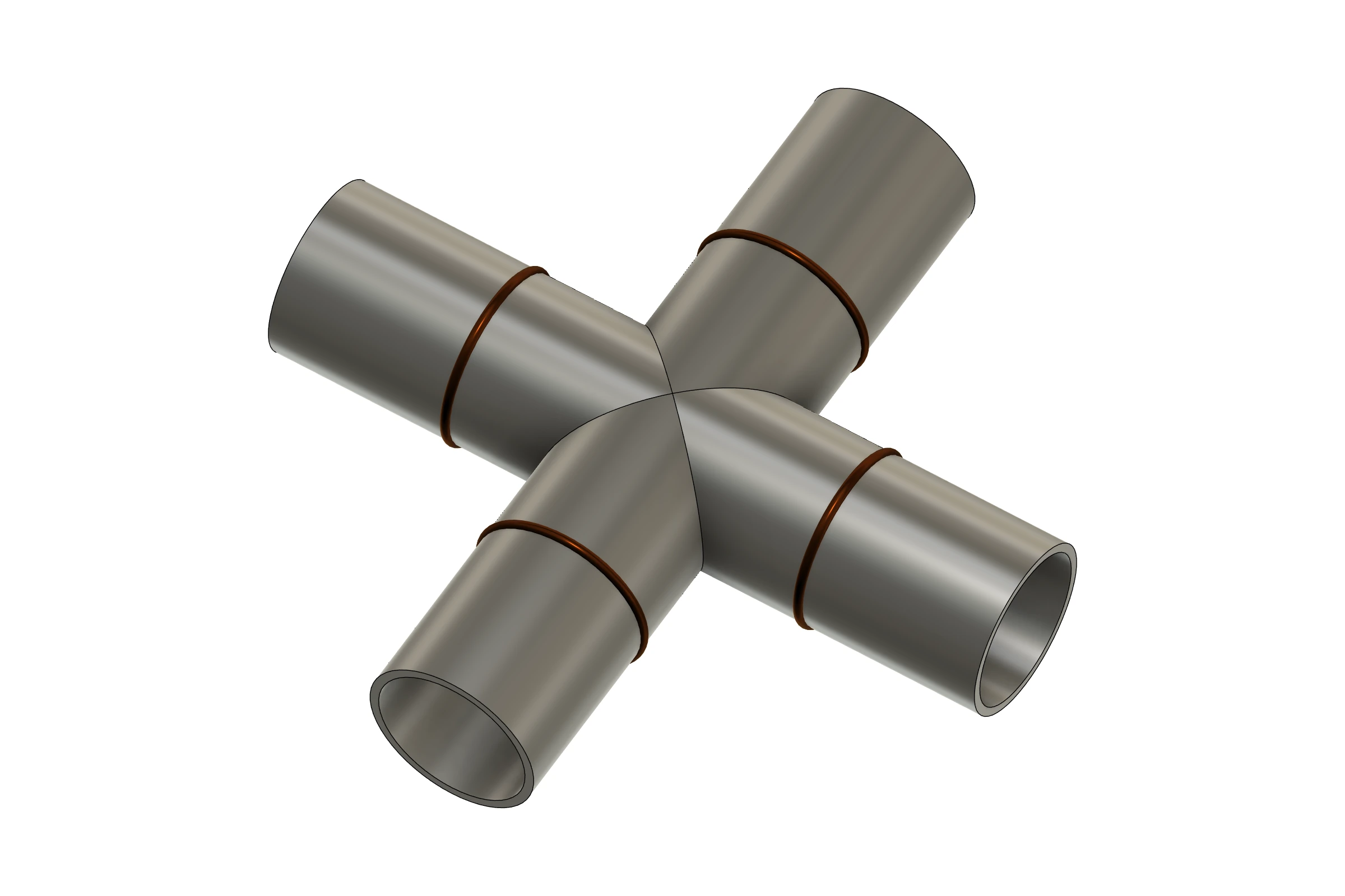
Connect four pipe directions at one junction.
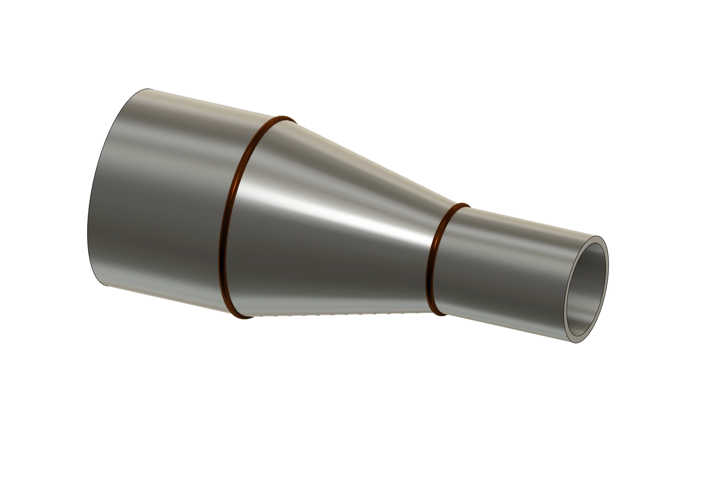
Transition between two diameters on the same centreline.
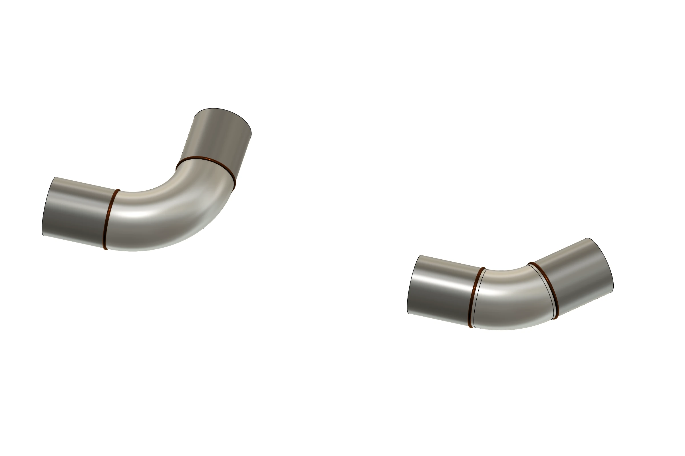
Change direction with a separate elbow fitting.
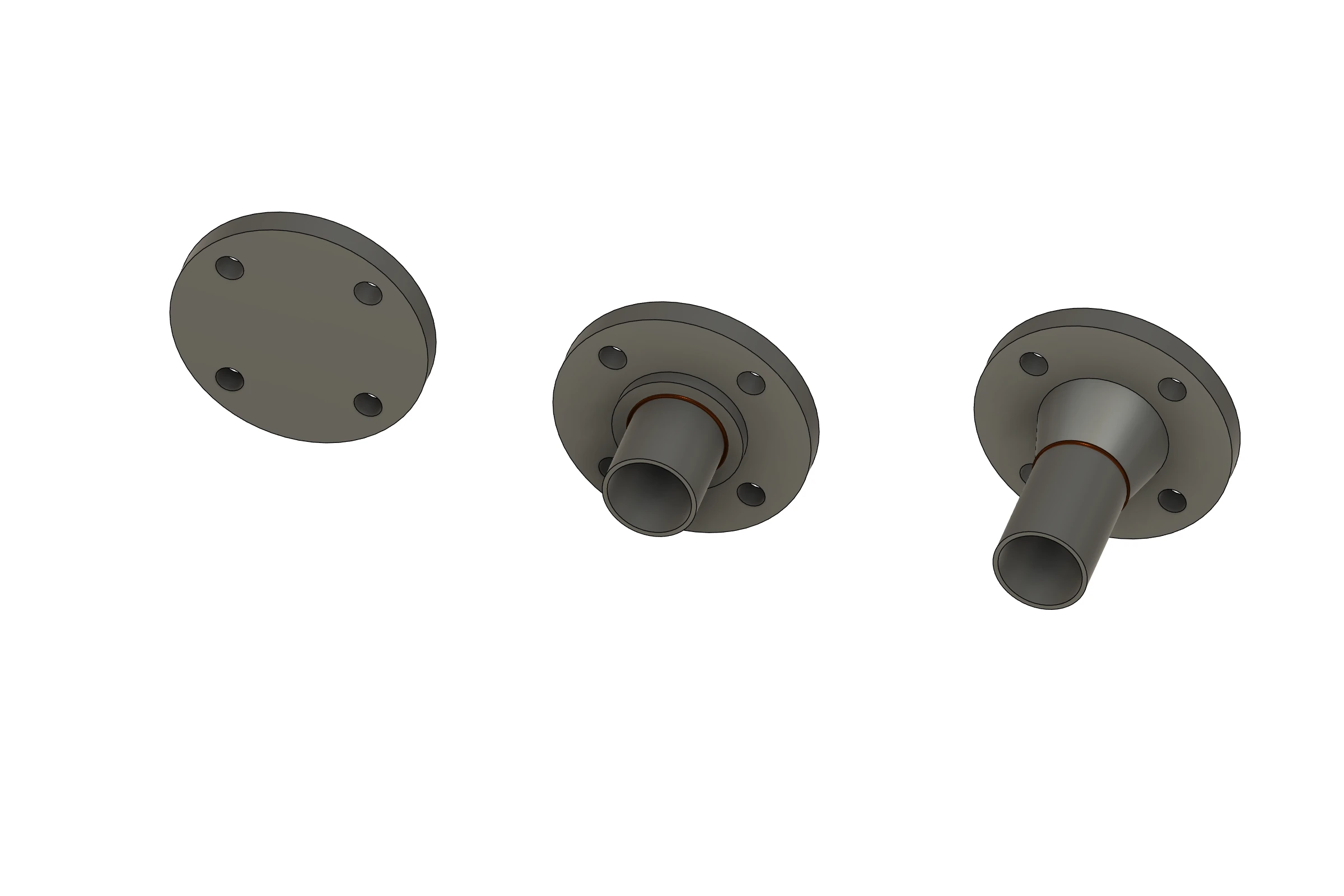
Compare three flange forms, from a pipe connection to a closed end.
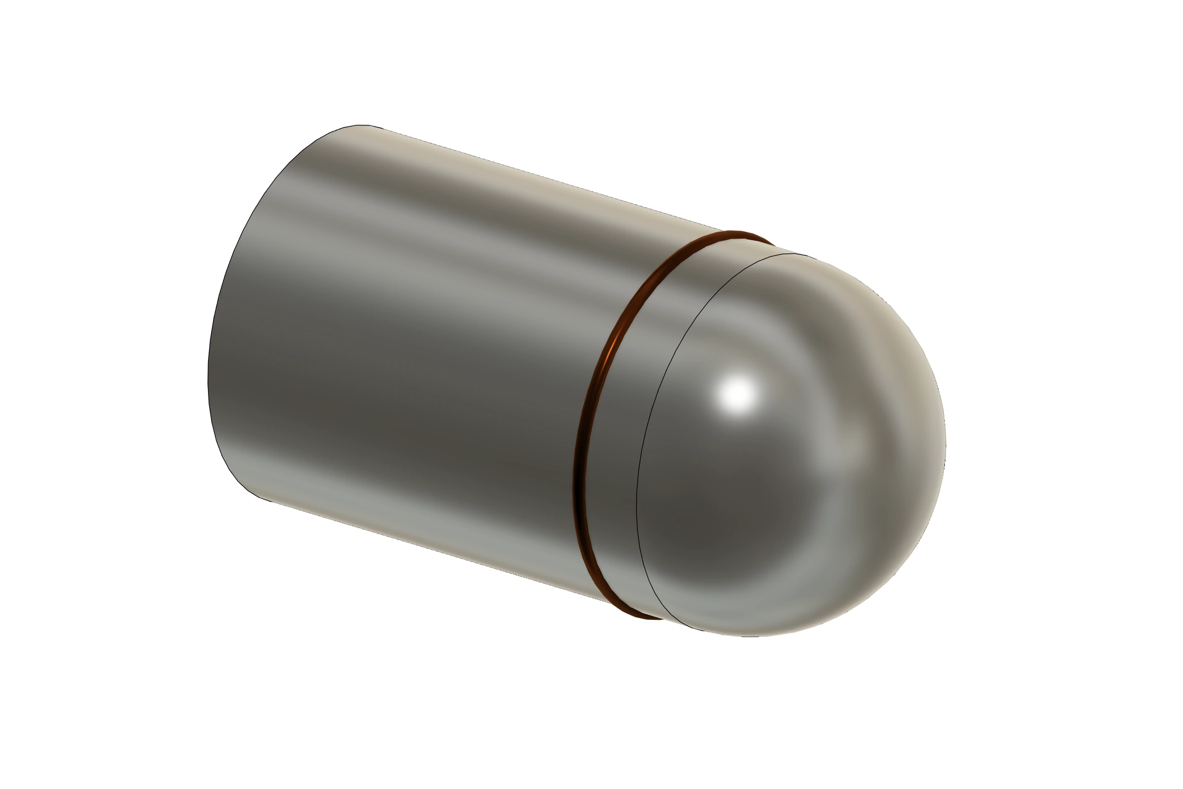
Close the end of a pipe branch.
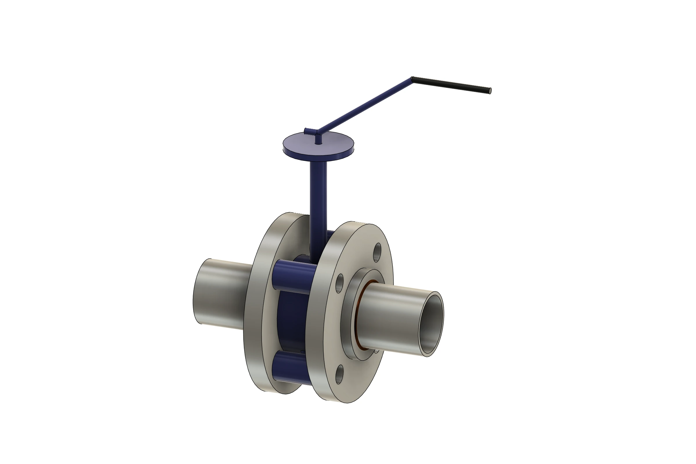
Place a wafer valve between pipe flanges and orient the valve to suit the layout.
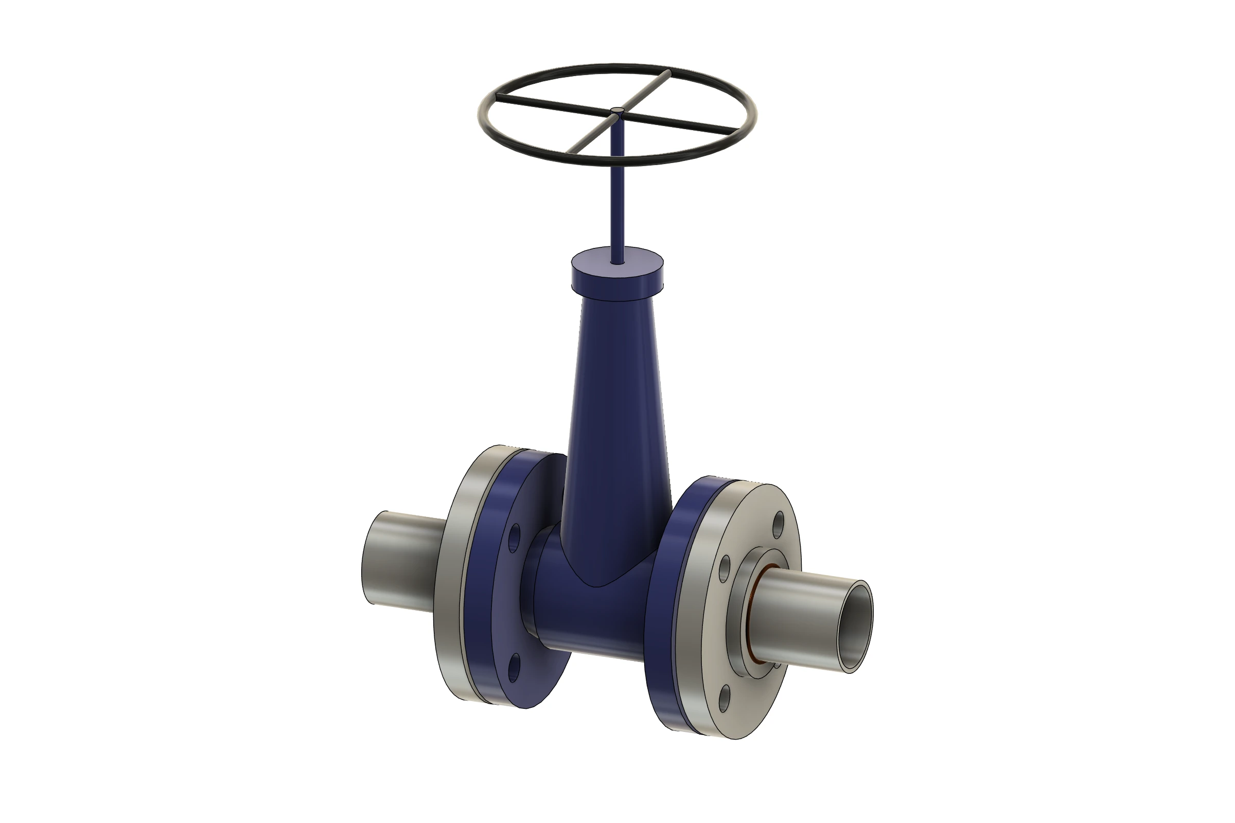
Set the face-to-face length and rotate the valve around the pipe axis. Shown with its two grey mating pipe flanges.
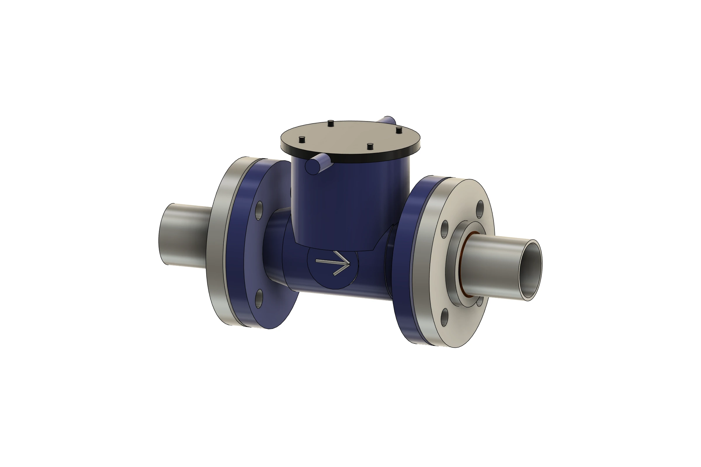
Show the intended flow direction and reverse it when the connection changes.
Butterfly, gate and check valve installation dimensions for DN50–DN200 follow Genebre 2103, AVK gate and AVK swing check catalogue drawings. Other sizes are marked as estimates. Casting contours and internal parts are simplified for layout. Check the purchased part.
Pipe Support
Pick the outside of a straight pipe to read its diameter. Position the support along the segment, rotate it around the pipe, or select a mounting face to align its base. Reopen a saved support to change its dimensions or placement.
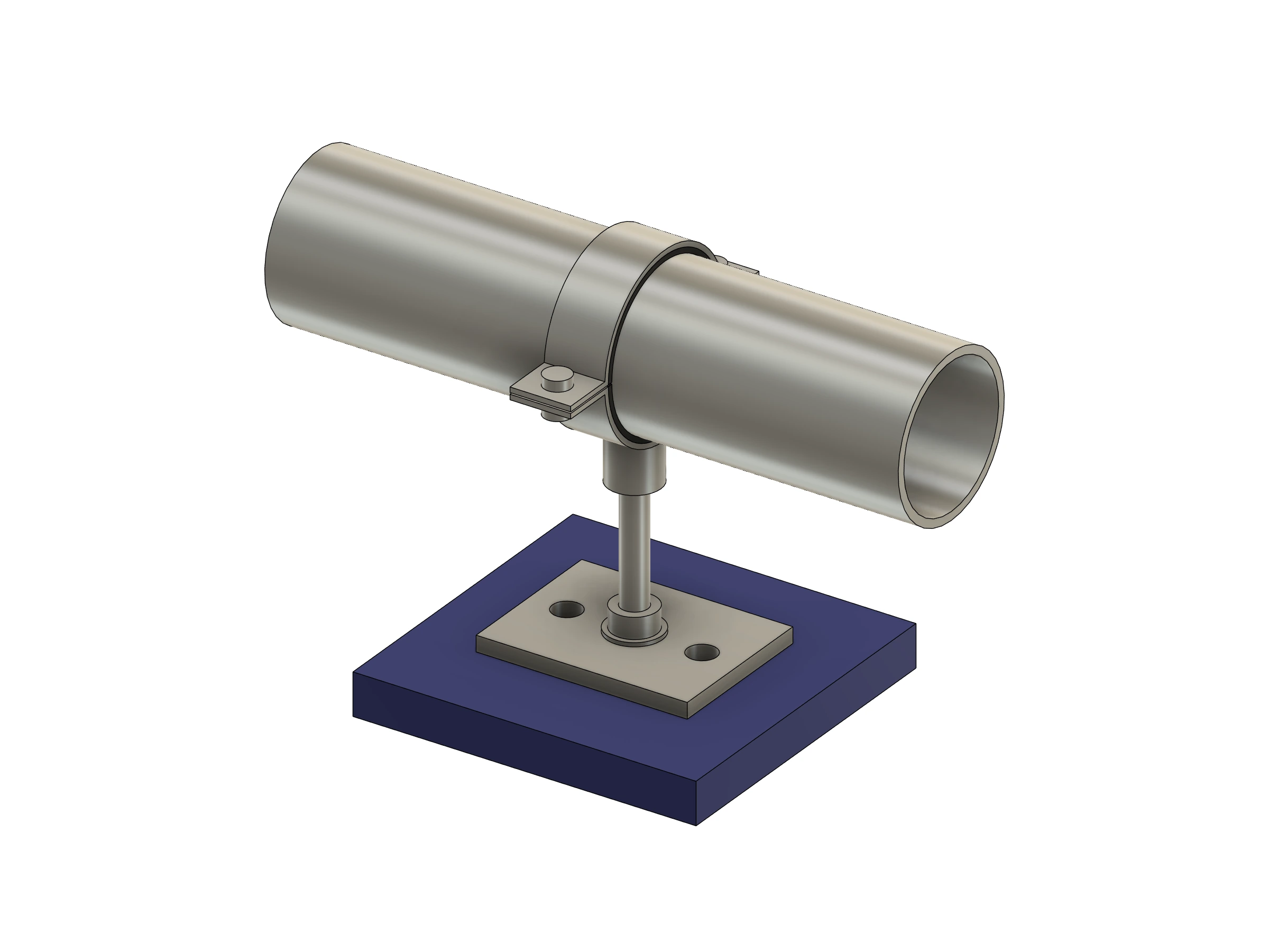
Two clamp halves, optional lining, and foot or threaded-rod mounting.
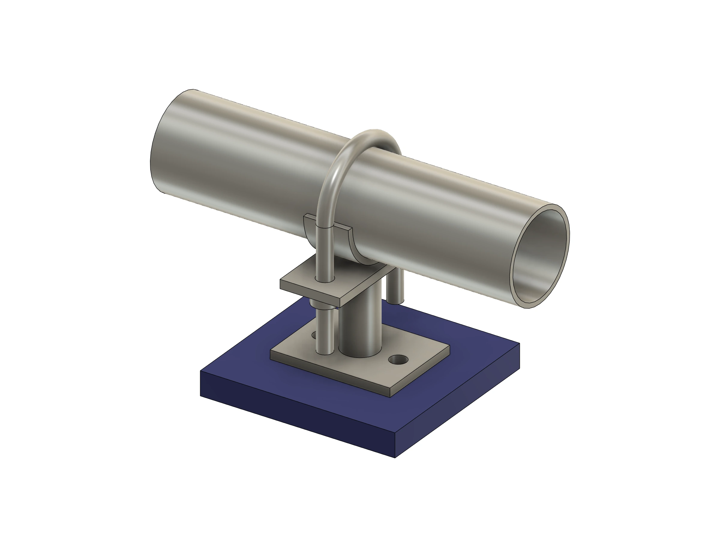
A curved U-bolt, saddle, nuts and a base plate for a visible mounting arrangement.
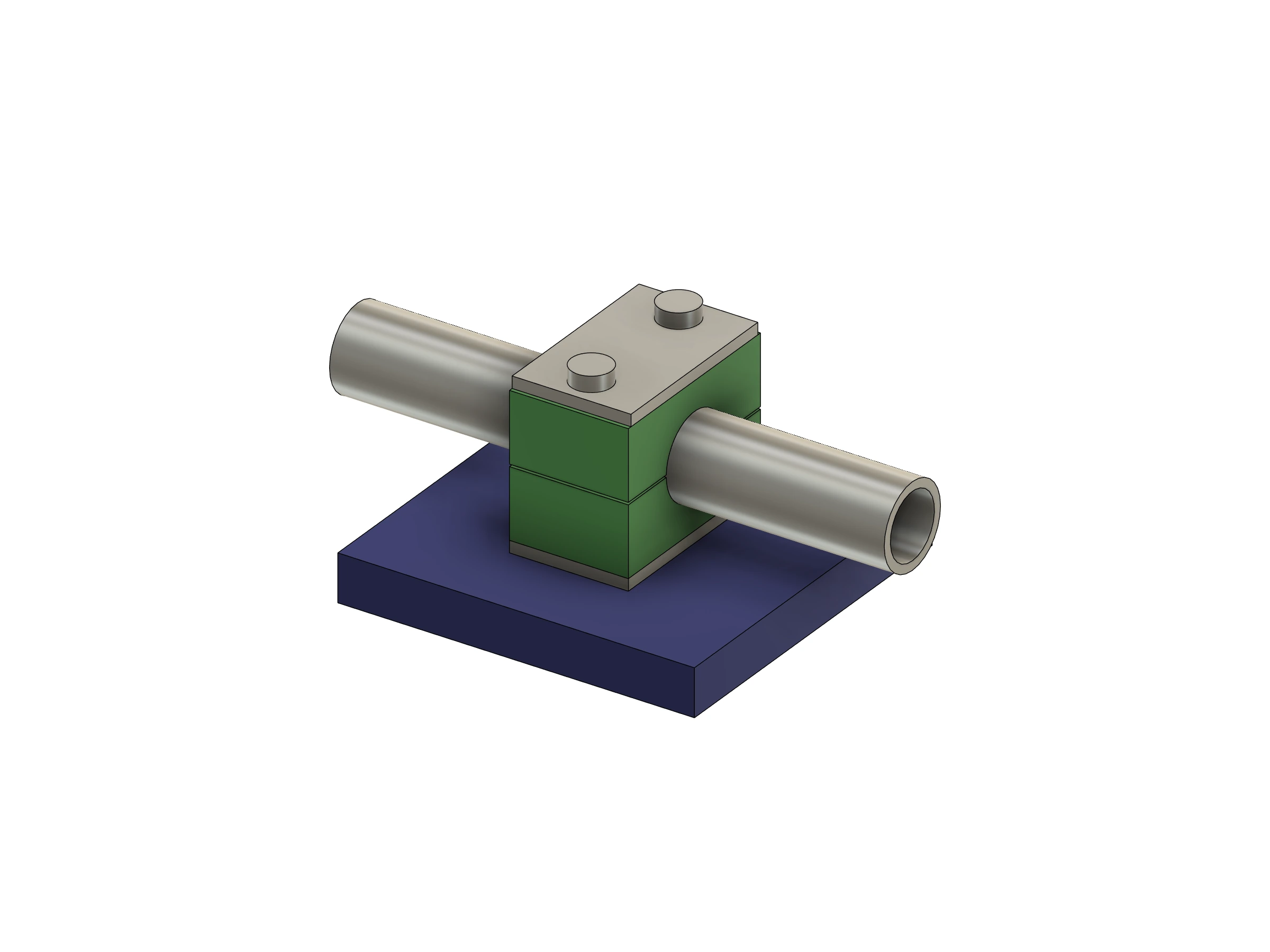
Block halves with a cover plate and weld plate, using referenced STAUFF series dimensions.
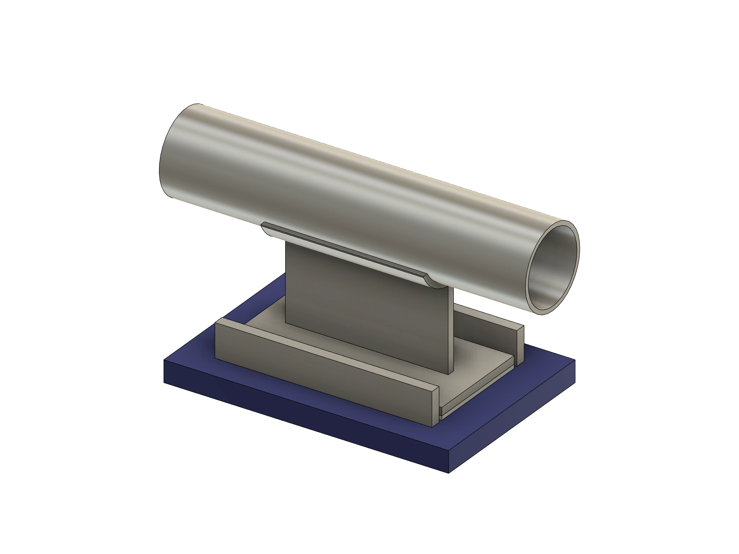
Adjust the saddle, web and base dimensions. Show fixed, sliding or guided arrangements.
Supports retain their source segment, station and matching moved or copied pipe instance when a linked route is rebuilt. A missing reference or an incompatible position is reported for review.
Import a vendor STEP into Fusion or model a bracket, then capture its component or solids with Support from Model. The stored assembly keeps its original dimensions.
Include support assemblies in a separate BOM, alongside the tube and fitting quantities. Support placement preserves tube cut lengths and pipe-joint weld estimates.
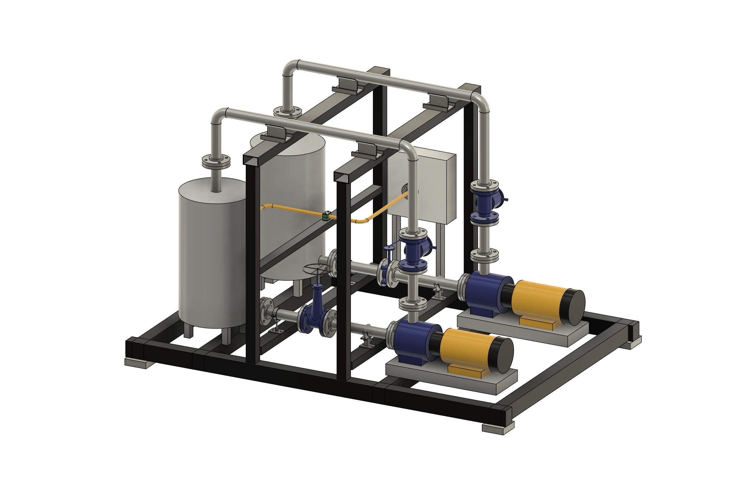
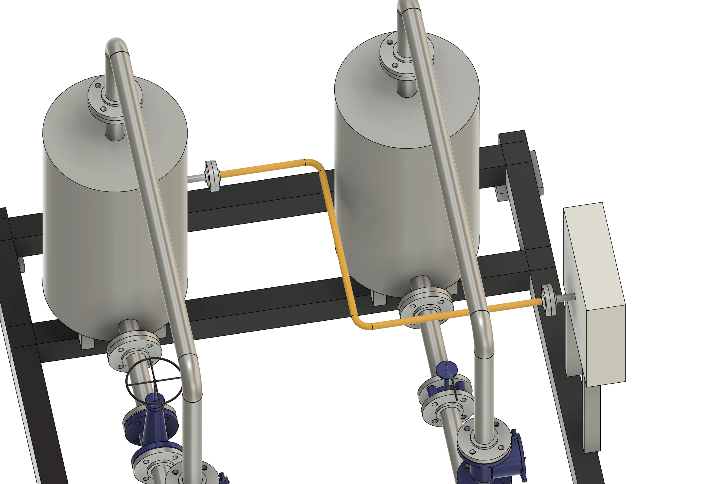
The skid at the top of this page contains two split clamps, two U-bolts, four guided shoes and one block clamp. Its export lists these nine assemblies separately from tubes and fittings. Equipment and the supporting steelwork provide assembly context and are not part of the tube BOM.
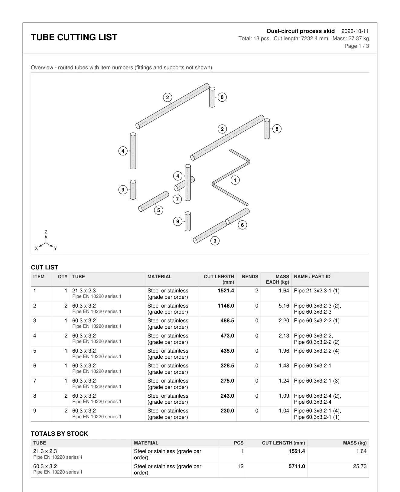
The cut list opens with an isometric overview of every placed tube and its item number, then lists tube and standard, material, cut length, bends and mass, with totals per stock. Purchased fittings, the supports and a weld summary follow; each bent tube gets an isometric view and bend table.
Material comes from the bender setup or the model, else from the tube standard, for example steel S195T for EN 10255 pipe or copper C12200 for ASTM B88 tube.
Referenced installation dimensions and adjustable fabricated dimensions are identified in the library. Models simplify threads and small manufacturing details. Choose spacing, fixed points and guides for your installation; support loads and thermal movement are not analyzed by this command. View pipe support dimensional presets and sources.
Recognize Tube
Recover the centreline and bend information from a supported hollow round tube. The original solid stays in place and is not rebuilt with Route Pipe, while the tube joins the reporting workflow.
Bend Data and package export recheck the source geometry. An unsupported later edit stops export rather than reusing old dimensions.
Open Recognize Tube and select the hollow round body.
Check the recovered path. Keep End A as the feed start or reverse the direction.
Open Bend Data, then include the recognized tube in your fabrication package.
Constant OD and wall, square-cut ends, straight leads and tails, and tangent circular bends below 180 degrees. Bends may lie in multiple planes.
Recognition does not cover solid bars, fittings, holes, coped ends, branches, closed loops, variable walls, meshes or freeform surfaces.
Read the recognition workflowRoute Pipe → Bend Data
This 25 × 2 mm tube was created from the downloadable LRA input. Its three bends change direction and radius; the last row defines the straight tail. The same tube is part TP00001 in the bend sheet, stock plan and fabrication package below.
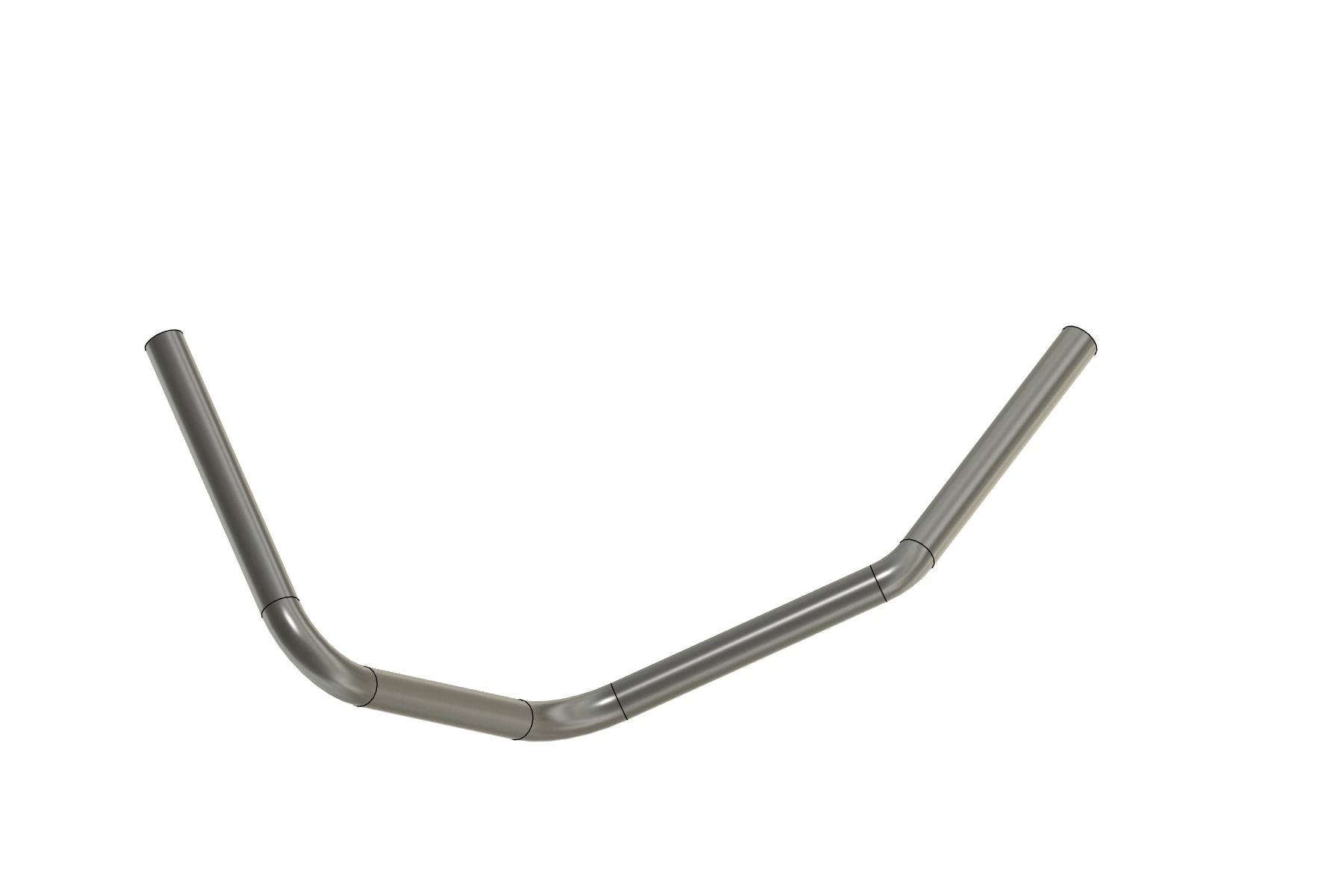
The input used for this model
Incremental rotation, CCW positive. First bend is the reference.
| Bend | Feed mm | Rotate ° | Bend ° | CLR mm |
|---|---|---|---|---|
| 1 | 200 | 0 | 90 | 50 |
| 2 | 150 | 90 | 60 | 70 |
| 3 | 175 | -120 | 45 | 40 |
| Tail | 200 | 0 | 0 | 0 |
End feed 200.00 mm
Developed cut length
908.26 mm
This example uses three radii to demonstrate per-bend input. Production needs suitable tooling for each radius; the add-in flags mixed radii for review.
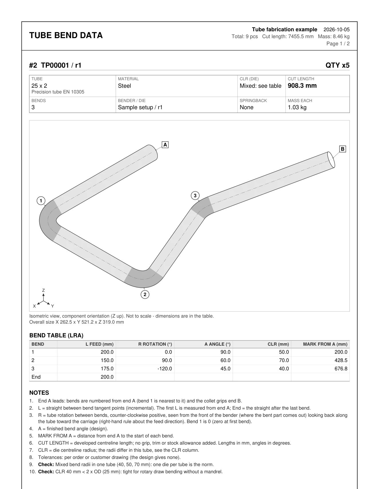
Bend Data also exports an A4 PDF with one sheet per unique bent tube: tube, material, CLR, cut length and setup; an isometric view with numbered bends and ends A and B; and the bend table with marks from end A. Numbered notes state which end leads, how rotation is measured and which angle to dial.
The CSV holds the same table to read or type into the bender. Neither file is a machine program.
Save a setup once and apply it to selected routes. Each assignment keeps its own revision, so editing the library does not silently change an existing design.
Enter springback compensation or fit commanded versus measured angles from your test bends. Review fit residuals and the measured angle range.
Set OD, wall and CLR restrictions, minimum entry/exit grip lengths, minimum straight between bends and maximum commanded bend angle. An assigned limit violation blocks manufacturing export.
Save the die mark offset and material density alongside the bend compensation.
Reports carry the assigned setup. Unassigned tubes use zero compensation and the density of their tube standard's material.
Compensation adjusts commanded angles; the die offset sets the marks. Neither changes the modeled tube.
Notch Template
Select the branch and target cylindrical faces, or enter the joint dimensions. Preview the cope, set radial clearance and export the unrolled cut line as PDF and DXF.
Print at 100% and measure the check bar.
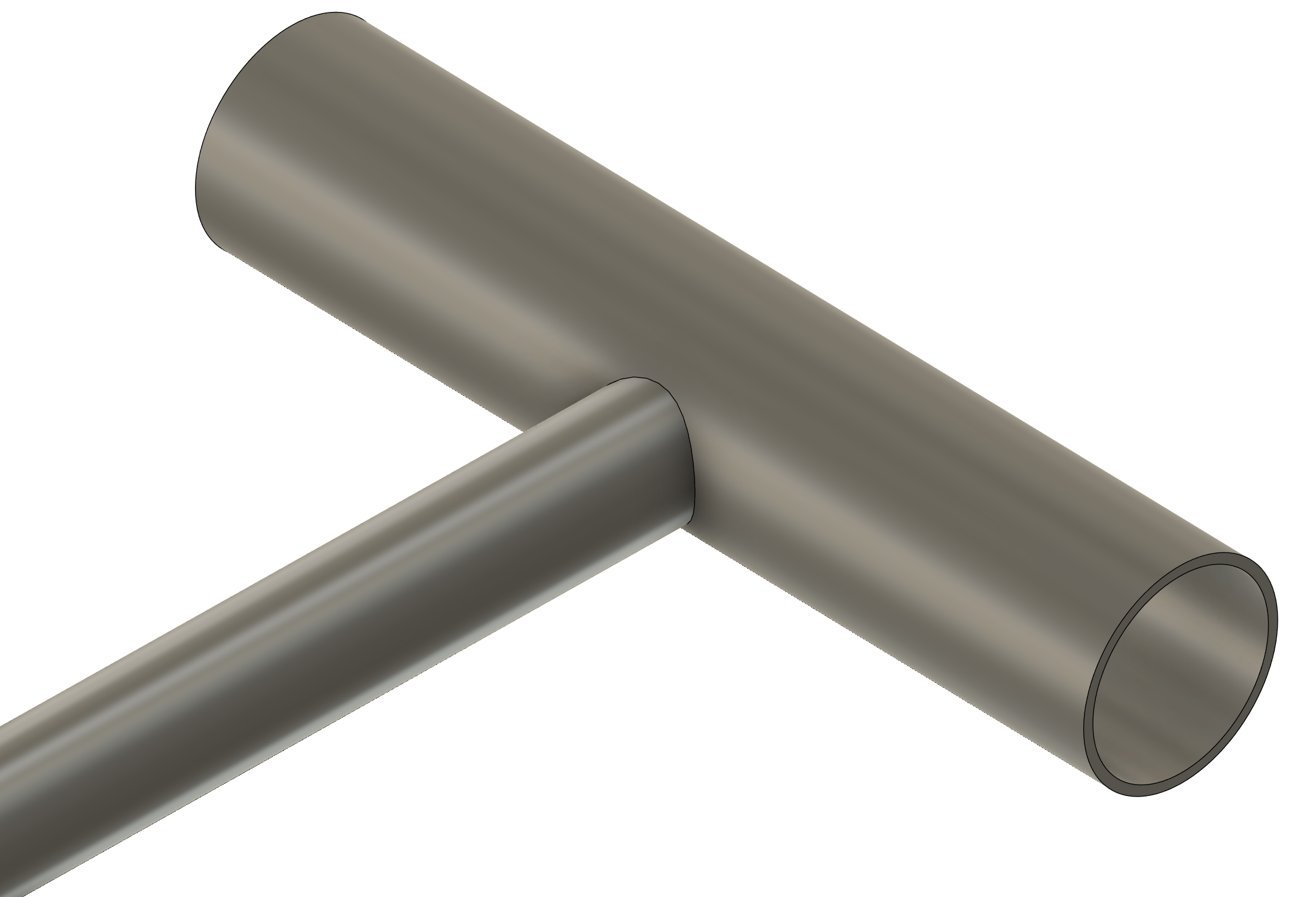
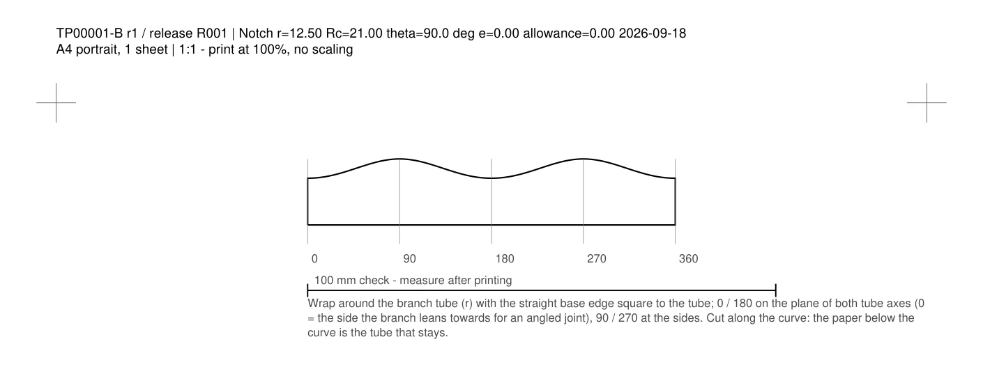
This separate sample package includes the saved End B template for its branch tube (part TP00001 in that package), revision 1. The joint uses zero offset and zero radial allowance; its wrap circumference is 78.54 mm.
See the coped end with the main tube hidden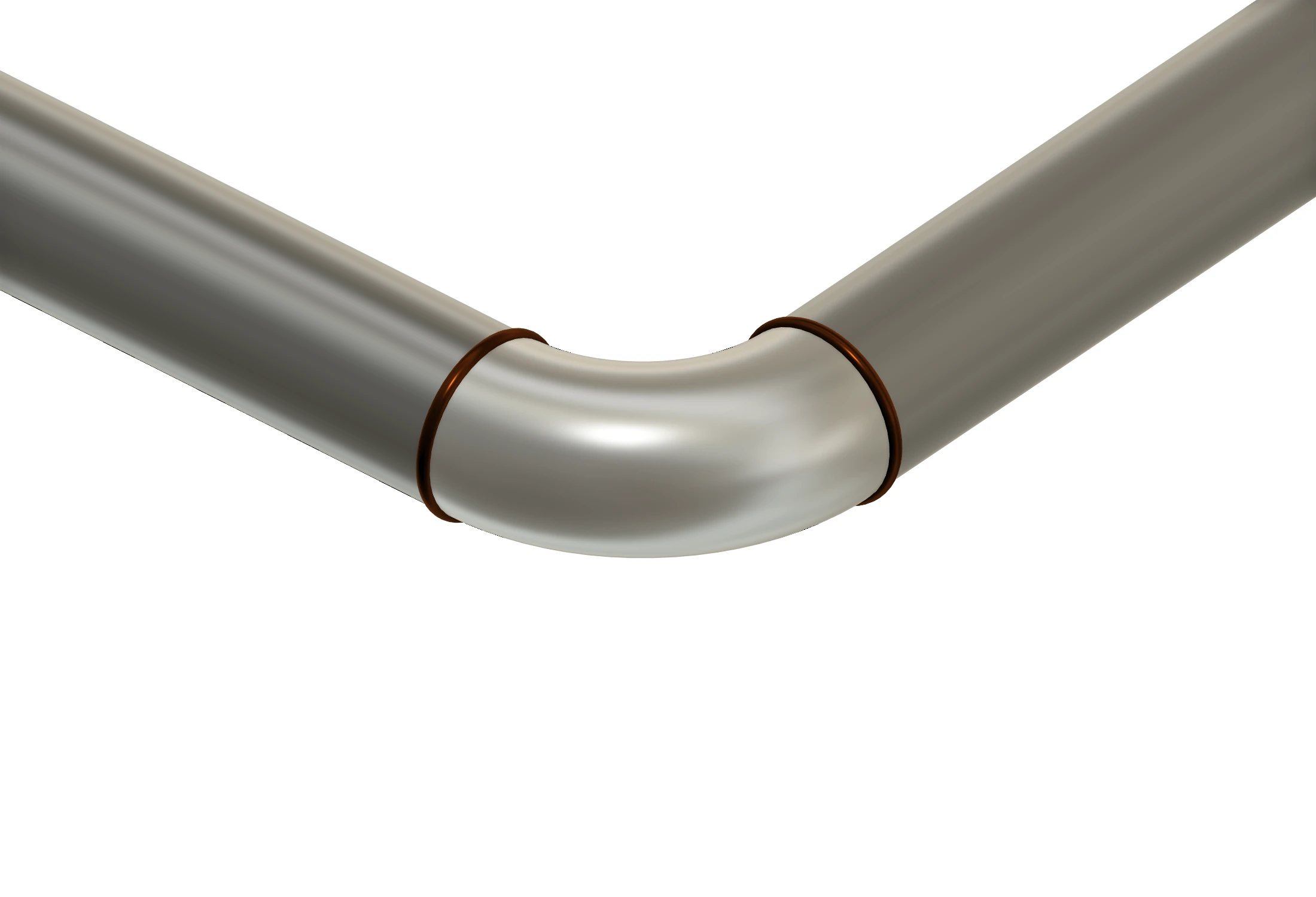
Weld Joints
Review the connections recorded at fitting ports and tube ends: butt welds, socket-weld assumptions, slip-on flange fillets and set-on branches. Exclude joints outside your scope and apply your labour and consumable rates.
Quantities use the command's assumed weld sections and steel density. Adjust rates and review the joint assumptions for your process; this is an estimate, not a weld procedure or pressure-design check.
Weld estimates and bead previews currently evaluate native route and fitting definitions. Repeated or nested assembly instances are not counted separately here; Cutting List and Fabrication Package quantities do include them.
Eight active joints and ten bead rings: the two slip-on connections have two fillets each. The two bolted valve interfaces are excluded. Labour and consumable rates in this example are illustrative.
Stock Optimizer
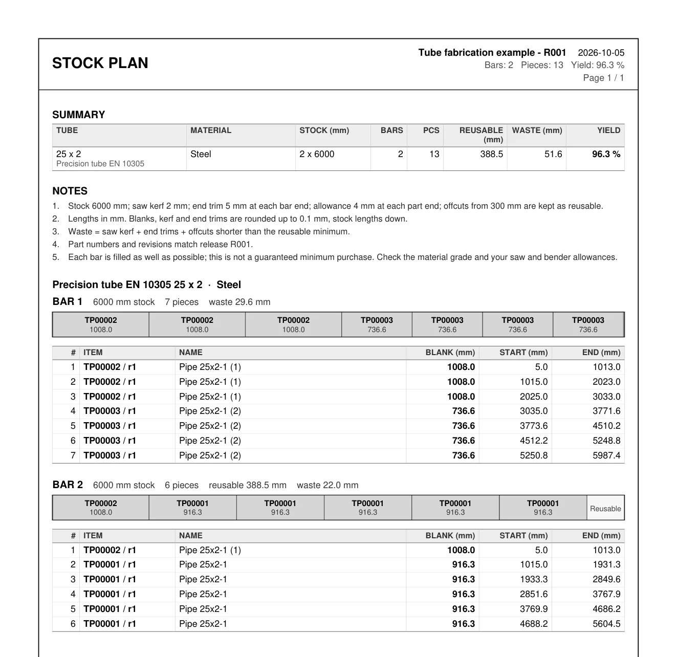
Enter your stock lengths, saw kerf, end trims and part allowances. The optimizer groups tubes by stock size and material, accounts for placed quantities and lays out the cuts on each bar. Export PDF diagrams and CSV cut positions, or include the plan in a fabrication release.
Project settings are saved with the design. Reusable tails are listed separately from waste. Available stock is unlimited by length; a finite offcut inventory and a guaranteed minimum purchase order are not included. Extra blank allowance does not shift bend marks.
Fabrication Package
Export one ZIP with stable part numbers, part revisions and assembly quantities. Its HTML index links the documents for each tube, while the change list identifies what changed since the previous release.
Three part definitions and thirteen tube instances: straight, planar and spatial tubes, per-part PDFs and STEP, plus the stock plan shown above. Setup values are illustrative. This package contains no fittings or saved notch templates.
Placed and nested component instances, and Paste New copies of a tube, contribute to quantities. Hidden components still count.
Geometry, setup and saved end changes revise the relevant part; quantity changes are tracked separately.
Save the Fusion design after export to preserve part numbering and the release history.
Export checks the current source sketch, fitting trims and tube geometry before using saved bend data. Saved notch ends must still match their source geometry. STEP provides geometry for your CAM workflow. The weld-cost estimate is exported separately.
Pipe and fitting libraries
Choose from EN / ISO, ASME / ASTM and JIS pipe and tube tables, including PVC-U, HDPE, PEX, copper, conduit, hydraulic and instrumentation tube, or add your own sizes by hand, from a cylindrical model face, through CSV or as shareable JSON library packs. Twenty built-in fitting types cover pipework, valves and mechanical connectors. Your sizes, packs, captured fittings, flange sizes and weld rates are kept outside the add-in folder, so updates keep them.
EN 10255, EN 10220 / ISO 4200 and EN 10305.
Common NPS schedules and JIS SGP, STPG, SUS and STKM families.
DOM, 4130 chromoly, exhaust, stainless and aluminium tube.
ISO 2037, DIN 11850, EN 1057 and ASTM B88 L.
PVC schedules, PPR PN10/PN20 and EN 39 scaffold tube.
EN, ASME and JIS flange tables, plus parametric pipe fittings and custom solids.
Catalog dimensions support layout and estimating. Simplified fitting bodies do not certify material, pressure rating or manufacturing tolerances; check supplier details before production.
Extended fitting library
Add sanitary tube ends or threaded pipe connections where the project calls for them. Catalogue connection dimensions set the pipe cutback, and manufacturer part codes stay with the fitting in the BOM.
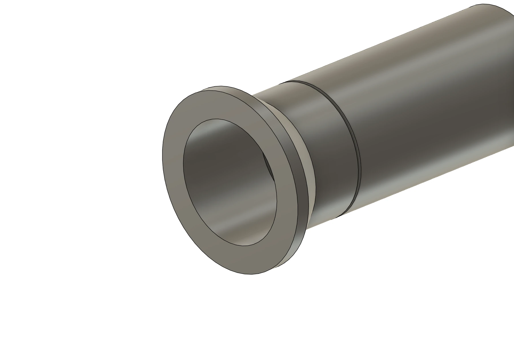
Three 316L ferrules for 25.4, 38.1 and 50.8 mm tube OD with 16ga wall (1.651 mm). The tube side has one butt weld. This is the ferrule only; a clamp and gasket are not included.
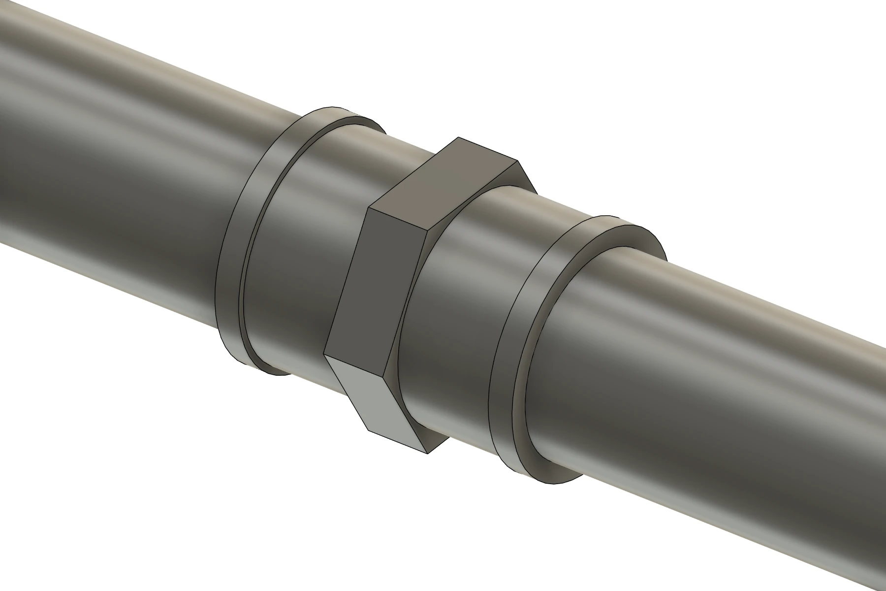
Five Rp female coupling sizes from 1/4 to 1 inch for matching R male pipe threads, on BSP pipe of 13.5, 17.2, 21.3, 26.9 and 33.7 mm OD. Cut lengths use the supplier’s mean make-up allowance; verify actual engagement before cutting. Other diameters and thread systems require a suitable custom fitting.
SMC KQ2 push-in unions fit the matching SMC TU polyurethane tube sizes in the Manufacturer library. They are not welded steel or stainless pipe fittings.
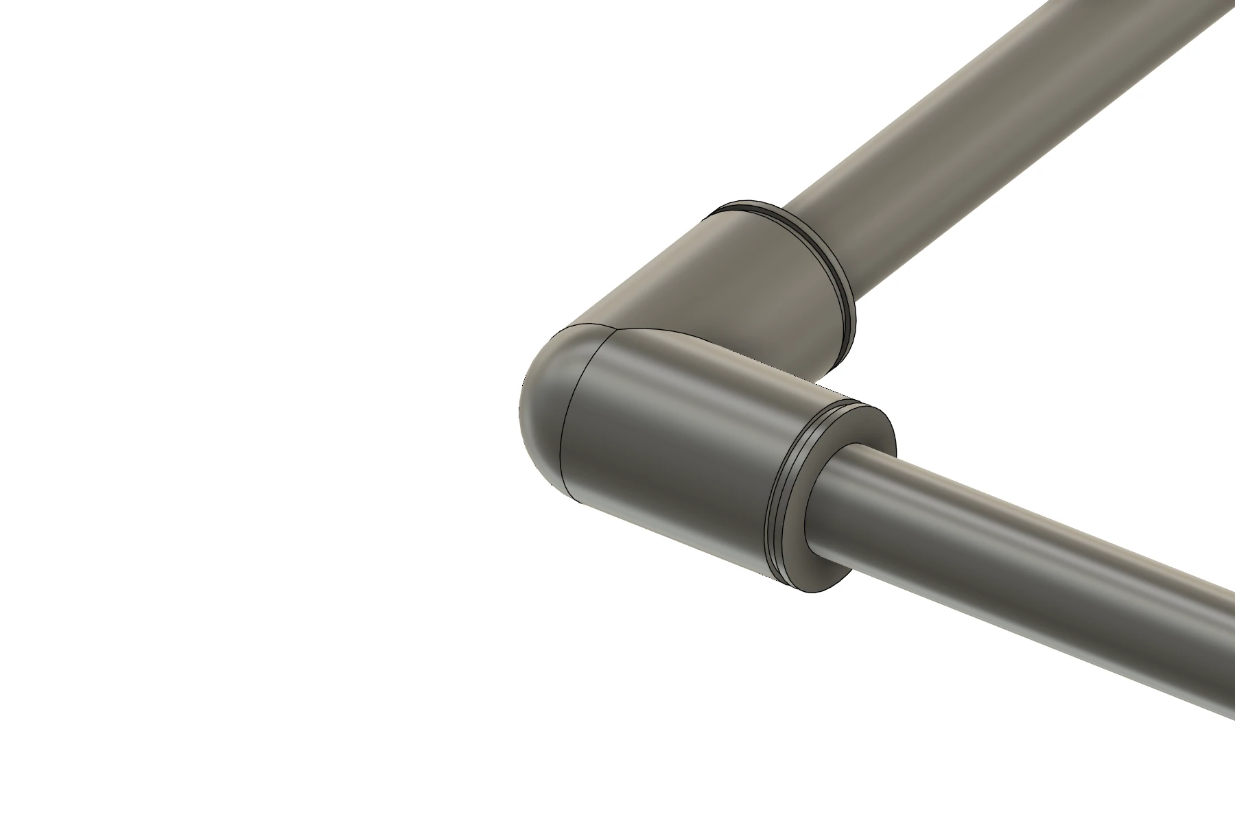
Join or turn 4, 6, 8, 10 or 12 mm OD tubing. Published insertion depths position the cut ends inside the sockets.
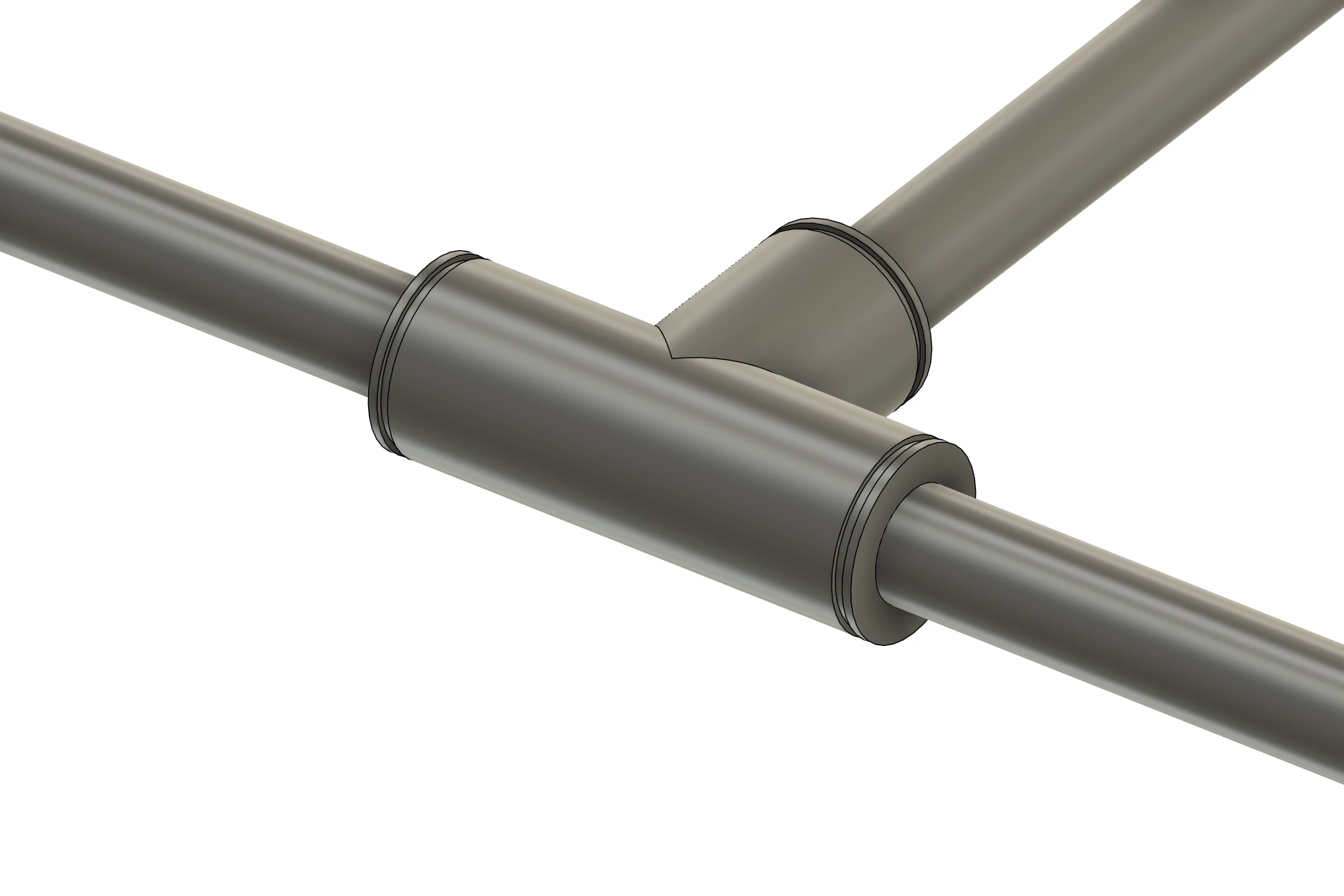
Branch an air line with three matching ports. Together with the straight and elbow unions, the library includes 15 manufacturer-coded sizes.
This workflow provides geometric layout, cut lengths and a fitting BOM; it does not simulate flexible-tube behaviour, kinking or air flow. Published tube bend radii are reference limits, not CNC bender settings.
The extension adds 23 manufacturer-coded connector entries and eight matching tube sizes, included in the library totals above. Installation dimensions follow supplier tables; exterior details and internal mechanisms are simplified.
View connector sizes and source drawingsThe Tube and Pipe ribbon
Find these tools in Fusion's Tube and Pipe tab.
Create
Build the pipework, place its connections and supports, or start from an imported tube.
Tubes from sketch paths or XYZ/LRA tables.
Elbows, tees, reducers, flanges, valves and connectors.
Your own solid as a reusable fitting.
Clamps, U-bolts, pipe shoes and custom supports.
Your own or imported support assembly.

Bend data from imported round tubes.
Orthogonal path around obstacles, with optional guide points.
Manage
Prepare bending and fabrication data, estimate pipe welds and maintain your libraries.
LRA/YBC and XYZ tables as CSV; A4 bend sheets as PDF.
Machine, die and material setups with compensation and limits.
Cut lengths, mass, fitting and support lists as CSV and PDF.

Bar cutting plans with kerf, allowances and reusable tails.
One revisioned ZIP of shop files per release.
Pipe weld quantities, time and cost; optional bead rings.
Fishmouth cuts and full-size wrap templates as PDF and DXF.
Add pipe and flange sizes by hand, from model faces or by CSV.

Open product help and links, check license status, or enter an activation code.
Get Tube & Pipe Routing
Pay by card through Lemon Squeezy with the email of your Autodesk account, with a free 3-day trial first. The license is issued to that account and unlocks the Windows and the macOS build; download it below with the same email. The Autodesk App Store listing is coming.
Read the current user guideUS$49 / year
or US$8/month, per user
A separate add-in from Weldments and Weldments Pro.
Ask a questionDownload
With a license (a purchase or a license from us), download the newest Windows or macOS build here with the email of your Autodesk account. The add-in checks your license when it starts, so the file is only useful with a license.
No license yet? Buy by email. Then install it with the installation guide.
The same add-in runs on Windows and macOS. Pick the machine you will install on.
Checking…
Adding the ZIP by hand? In Scripts and Add-Ins › +, select the folder that contains the .manifest file, not the file: on Windows, the Contents folder inside the .bundle.
Updating or switching versions? Clear Run on Startup for the old add-in, Stop it and close Fusion before replacing files. Restart Fusion before you Run the new version.
Yes. The build runs in Autodesk Fusion on Windows and macOS, and both bundles are published for every version. One subscription unlocks both.
No. The CSV and the PDF bend sheets are for people: LRA/YBC tables and XYZ coordinates with the conventions written out, for an operator or programmer to enter. CNC benders load typed values, a STEP model of the bent tube (the per-part STEP in a Fabrication Package) or a maker-specific format; a machine-specific postprocessor is not included. Calibrate compensation with test bends and verify the first part.
Yes. Recognize Tube reads supported hollow round tubes with constant OD and wall and tangent circular bends; holes, copes, branches and freeform surfaces are not supported.
Yes. Capture the supplier's solid with Fitting from Model when you need its exact shape; the 20 built-in fitting types, four valve forms among them, are simplified for layout.
Yes, for supported built-in flanged and wafer valves: enable Add mating flanges.
Yes. Route Pipe imports XYZ apexes or nominal Length/Rotation/Angle rows, with an optional radius per bend. The input is a numeric table, not a CNC program or the annotated Bend Data export CSV.
Yes. Independent copies and nested repeated parents keep their placements; pieces that cannot be replaced safely are reported and kept intact.
Yes. Pipe Support places clamps, U-bolts and pipe shoes on straight pipe. Support from Model captures your own bracket using a cylindrical pipe-seat face and a planar mounting face; an imported assembly needs a matching pipe outside diameter.
No. Supports leave tube cut lengths and pipe welds unchanged, and you choose their spacing; the add-in checks placement, not allowable spacing, thermal expansion or loads.
No. Built-in valve faces and blind-flange interfaces are left out of the weld estimate, while the pipe-side flange welds stay; review custom fittings against their actual joining method.
One ZIP per release with an HTML index, cut list, per-part shop PDFs and bend CSVs, saved notch templates, a change list and a manifest, plus optional STEP and stock plans. Machine-specific programs are not included.
The bounding boxes of the obstacles you select, or of all visible bodies when you select none, with the pipe radius and your clearance added.
There are 23 manufacturer-coded entries: SMC KQ2 straight, elbow and tee push-in unions for 4 to 12 mm tube, GF 8270 BSP couplings from 1/4 to 1 inch and Alfa Laval L14AM sanitary ferrules, with matching SMC TU and sanitary 16ga tube in the Manufacturer library group.
Push-in pipes are cut to the published insertion depth and BSP pipes to the supplier's mean make-up allowance, with no weld gap and no weld; a sanitary ferrule counts one pipe-side butt weld and none at its clamp face.
Yes, as layout: five SMC TU polyurethane sizes come with published minimum bend radii, and flexible-tube behaviour is not simulated. Use an appropriate material density for mass estimates, and check the tube and connector operating limits for your application.
Tube & Pipe Routing focuses on round-tube and pipe fabrication: routing, fittings, bending, imported-tube recognition, stock cutting plans, notch templates and pipe-joint estimates. Weldments Pro focuses on structural frames, profile joints, weld modelling, frame analysis, stock optimization and plate fabrication. They are separate add-ins.
Your workflow
Tell us the machine you bend on, the stock and fittings you use, and the output format you need. A sample drawing or a small Fusion model helps us understand the job.
Already sent feedback?
My Reports →More for Autodesk Fusion (Fusion 360)
Frames, joints and cut lists
 Steel Frame & Weldments Pro
Tube folding, welds and frame analysis in Fusion
 Sheet Metal & Press Brake
Bend sheets for the press brake, from the Fusion flat
 Hole Series & Fasteners
Matching holes and bolts in every part
 Auto Backup & Export
Local backups of your Fusion cloud designs