Autodesk Fusion add-in · v1.0.0 · Windows · Early access

Sheet Metal & Press Brake icon

Sheet Metal & Press BrakePress Brake Bend Order, Back-Gauge & Setup Sheets for Autodesk Fusion (Fusion 360)

From the Fusion flat pattern
to the press brake.

Select a sheet-metal part. Sheet Metal & Press Brake reads the Fusion flat pattern, finds a bend order and the punch and die for it, down to the pieces of a sectioned set, and gives the back-gauge X, the handling and the checks for every hit, with your own tooling. Any step can be watched in 3D, and the whole plan checked in 3D against the punch, die and beam. The operator gets one bend sheet; the shop also gets a bend-program CSV and a layered flat DXF. Forms and Tab and Slot joints are added to the part in Fusion.

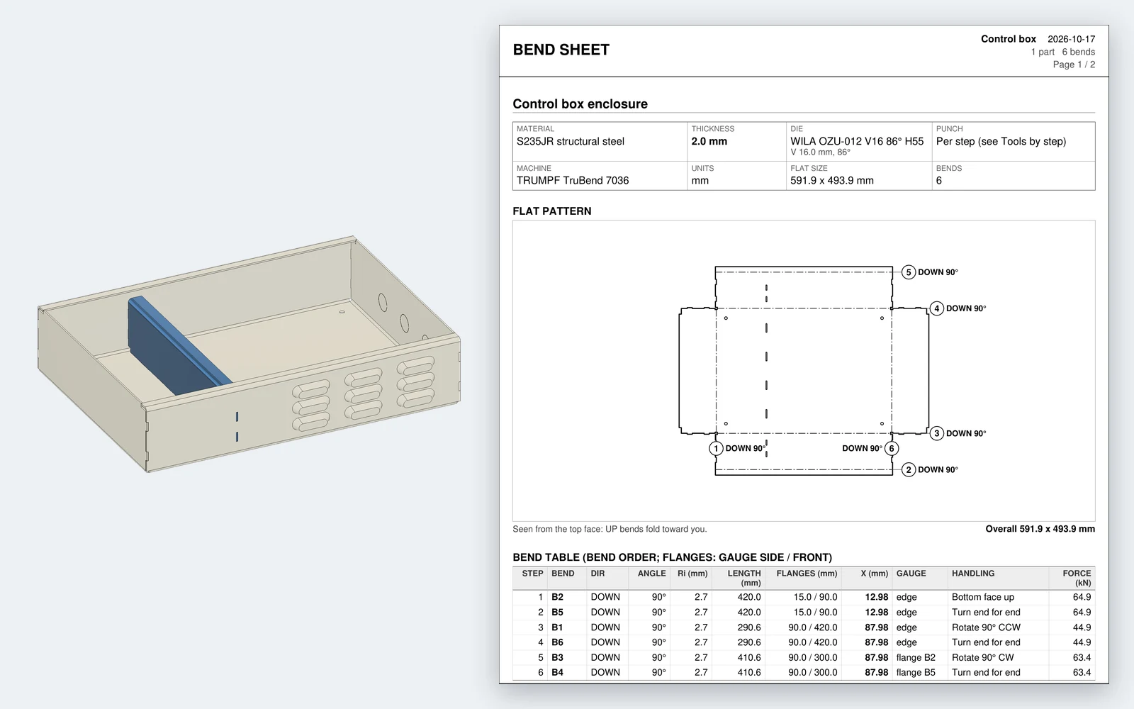
A Fusion sheet-metal enclosure with louvers, knockouts and a mounting plate next to its bend sheet: setup block, flat pattern with numbered bends and the bend table with back-gauge X and handling for six steps

A 2 mm control-box enclosure modelled in Fusion and the bend sheet the add-in wrote for it.

Every hit
back-gauge X and handling
Checked in 3D
part, punch, die and beam
Your tooling
its outlines and sectioned sets
One sheet per job
PDF, CSV and layered DXF

What it does

Fusion draws the flat. The brake needs more than that.

Fusion unfolds a sheet-metal part, draws its bend lines, exports the flat and puts bend tables and bend notes on drawings. What happens at the brake is left to the shop: which bend first (the bend sequence), where the back gauge goes for each hit, how the part is turned, whether a formed flange hits the punch. That is the part this add-in plans.

Switching CAD or planning bends at the machine

Coming from Inventor Bend Order, SolidWorks Sheet Metal, or manual press-brake setup?

Bend sequence (bend order) & part handlingNative Fusion by handNumber bend callouts manually on a 2D drawing; no flip or rotation planWith the add-inAuto tools + order searches your punch & die library for a clear bend sequence and writes the flip/turn handling per hit
Backgauge X (back-gauge stop) calculationNative Fusion by handComputed by the operator at the machine or in external offline CAMWith the add-inCalculates back-gauge X and gauge reference (edge or formed flange) for every step in Fusion
Punch, die, upper beam & box-wall collision checkNative Fusion by handInspect visually or discover interference during test bendingWith the add-in2D section sweep on every plan + full 3D solid refold check across the stroke and withdrawal
Checks before the first hitNative Fusion by handFound at the brake: a flange that falls into the die, a punch angle too sharp, a hole that distortsWith the add-inFlange length against the die, die and punch angles, force against tool and machine ratings, holes and forms near bends, flagged on the bend sheet
Tool dataNative Fusion by handLook up each punch and die in the catalogue and type it inWith the add-inA starter library of published catalogue values, every tool and machine with its outline, ready for the first bend sheet
Sectioned punch & die stationsNative Fusion by handPieces picked and spaced by the setter at the machineWith the add-inA station for every step from your sectioned sets: over the bend line, clear of the formed walls, horns at walled ends, written on the bend sheet
Die-driven K-factor & bend deductionNative Fusion by handType an assumed K-factor and inside radius into Sheet Metal RulesWith the add-inApply Bend Rule from your chosen V-die & punch, or Calibrate from Test Bend using one measured test strip
Louvers, knockouts, ribs & Tab and Slot jointsNative Fusion by handModel each feature and matching slot cut manually in sketchesWith the add-inParametric Create/Edit/Pattern Form tools checked against the tool makers’ limits, and Tab and Slot joints (including closed, tab-locked box corners)
Punch-press setup of a formed blankNative Fusion by handForms up or down and the hit order decided at the turretWith the add-inA shop plan with every form up or down as loaded and the hit order, checked hit by hit and shown in 3D
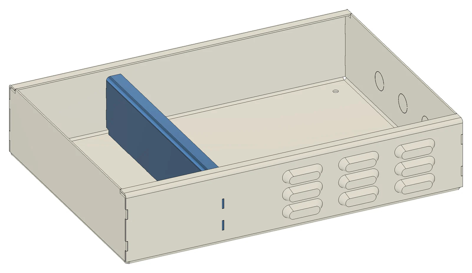
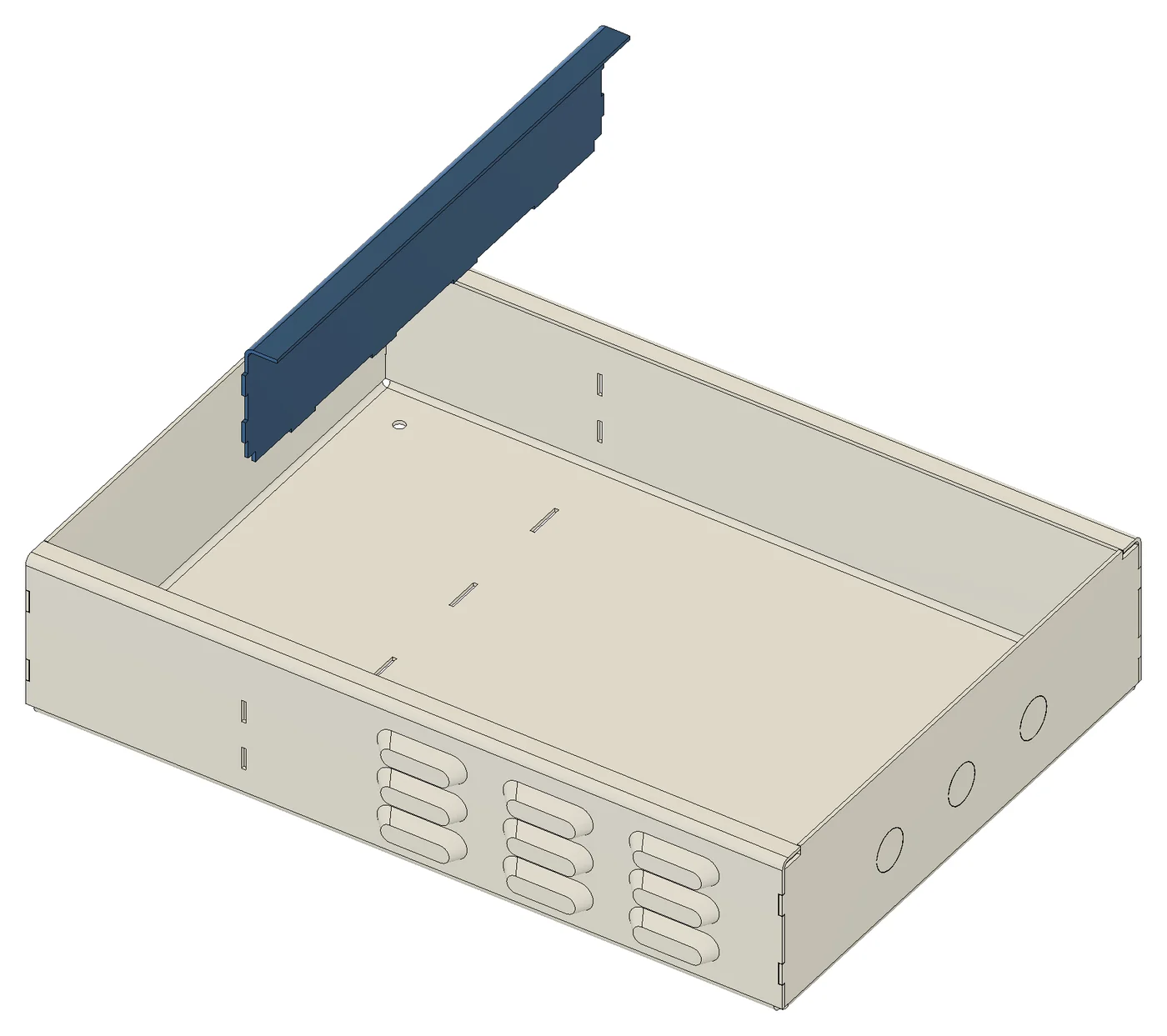
A 420 by 300 by 90 mm sheet-metal enclosure in Autodesk Fusion with closed, tab-locked corners, return flanges on the long walls, nine louvers in the front wall, three knockouts in the end wall and a blue mounting plate held in slots
The example on this page, as modelled in Fusion.

One real part, from start to finish

The enclosure is modelled with Fusion's own sheet-metal tools, closed corners included. Every picture of it below comes from that one design and the add-in's own commands. Three more parts with four to six bends follow under Example parts.

Part
Control-box enclosure, 420 × 300 × 90 mm
Material
S235JR steel, 2 mm
Corners
Closed: the long walls cover the end walls
Bends
6, including two 15 mm return flanges
Forms
9 louvers opening downwards, 3 cable knockouts
Joints
8 tabs hold the mounting plate, 8 lock the corners
Brake and tools
TRUMPF TruBend 7036; WILA V16 die, 120 mm punch and 163 mm gooseneck

Collision check

Collisions found in Fusion, in 2D and in 3D

A flange that swings into the punch as it rises, a return or a corner that hangs over the end of the punch, a wall that leaves the punch no room: every step is checked against the outlines of your punch, die, upper beam and back gauge, with the earlier bends formed. The check works at three levels, from the section check that every plan gets to the real part folded in 3D.

Section check of every step

The section across each bend is swept through the stroke: the back gauge retracts, the punch bends and withdraws. In a box, the punch length is checked against the walls at both ends. It runs on every plan; contacts go on the bend sheet with the step and the angle.

3D view of a step

Any step of the plan drawn beside your model, at any point of the stroke.

3D check of the plan

One button refolds the real part from its flat and checks every step of the plan in 3D.

Motion through step 5 of the control-box enclosure on a 120 mm gooseneck punch: the back gauge retracts, the walls rise, and before they reach 60° both flanges touch the upper beam, drawn red; then the punch withdraws.

Any step in 3D, every step checked in 3D

Tick Show the selected step in 3D and the dialog draws the step chosen in the table beside your model: the part refolded from its flat to that point of the stroke, on the die, under the punch and the see-through upper beam. Drag Motion through the back-gauge retract, the bend and the withdrawal; Go to the contact jumps to the first contact found. Where the part cuts into a tool, the shared volume is drawn in solid red and the tool turns see-through red. Nothing is added to the design, and the camera returns when the view is switched off.

Check all steps in 3D folds the real part, the flat body cut at its bend zones, step by step in the order of the table and tests it against the punch, die and beam as solids, every 5° of each bend and through the withdrawal. It takes a few seconds a step, with a progress bar and Cancel. Contacts are listed in the checks, in the bend-program CSV and on the bend sheet.

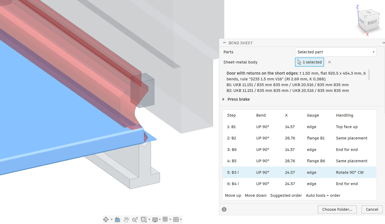
The Bend Sheet dialog in Autodesk Fusion with its 3D view switched on: a cabinet door lies on the die under a gooseneck punch drawn see-through red, the upper beam see-through grey behind it, and the bend table with steps 5 and 6 flagged
Step 5 of a door with returns on its short edges: the 3D check finds the end of the punch landing on a return.
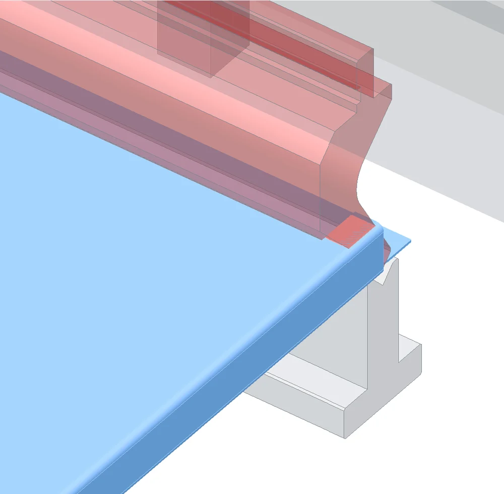
Close view of one end of the door on the press brake: the short wall with its return bent inwards at the top, the end of the gooseneck punch standing on the return, and the volume they share in solid red; the V die below
The end of the 835 mm punch lands on the return of the short wall (red).

What a section across the bend cannot see

A cabinet door, 400 × 832 mm in 1.5 mm steel, with returns on its short edges, bent short edges first: B1, B2, B6, B5, then the long walls B3 and B4 with the 835 mm punch. The section across a long-wall bend holds no return, so the section check cannot see the returns; it flags steps 5 and 6 for another reason, the punch being longer than the 832 mm between the bends of the short walls.

The 3D check finds what the section misses: the returns are bent inwards at the top of the short walls, and the ends of the punch come down on them at the very start of step 5 and of step 6. Auto tools + order bends the short walls first, then the long walls, then the returns between them on a 395 mm AMADA station: its first plan, a 67 mm punch on the returns, met the upper beam in 3D, so it took the 120 mm AMADA 804, and the plan it keeps is clear in the section check and in 3D.

A narrow U channel: the first flange meets the punch in the second bend

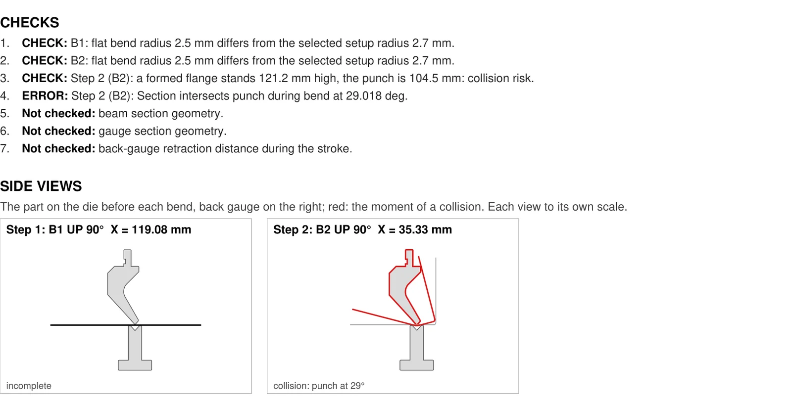
A narrow, deep U channel with a gooseneck punch, bent in the order the designer typed: after the first bend, the 121 mm flange stands higher than the 104.5 mm punch, and the section check finds it meeting the punch 29° into the second bend. The side view draws the part and the punch in red at that moment. Change the order or the punch and check again, or let Auto tools + order try the library.

Every check uses the outlines of the tools and the machine from the Press Brake Library; an outline that is not exact is named under Assumed on the bend sheet.

Checks of a bend sheet with an error that the section intersects the punch during bend 2 at 29 degrees, and two side views: step 1, and step 2 with the part and the gooseneck punch drawn in red at the moment of contact
From the bend sheet of the narrow U: the error, the warnings and the side views, the collision in red.

Auto tools + order

One button looks for a bend order and the tools to make it. It starts with the punch and die chosen in the dialog, then tries straight punches and dies near 8 × thickness, acute tools only when the part has an acute bend, both back-gauge sides and other bend orders, checking each step with the earlier bends formed. A tool change is listed per step when one is needed. It stops as soon as no better plan can exist, usually within a few seconds, and never runs longer than eight; the plan it keeps is checked again at the full resolution and then folded in 3D. A step whose part meets the upper beam there is searched again with taller punches or in another order, one that meets the punch or die with other tools; each check in 3D takes a few seconds a step, about a minute in all for the enclosure above. When no plan clears in 3D, the one with the fewest such steps is kept and its 3D check names them. A result that depends on missing tool data is marked provisional; an unsuccessful search does not prove that special tooling is needed.

Example parts

Parts where the order and the punch decide

Three more parts besides the enclosure, modelled with Fusion's sheet-metal tools and planned on an example 40-tonne brake whose beam and back-gauge outlines were entered in the library, as you would enter those of your own machine, starting from the UKB punch and die of the starter library. Each one was checked twice: in the order its bends were drawn, B1 first, and with Auto tools + order, whose plans are clear in the section check and in 3D. Under each part are its flat pattern and the step where the punch matters, both from its own bend sheet.

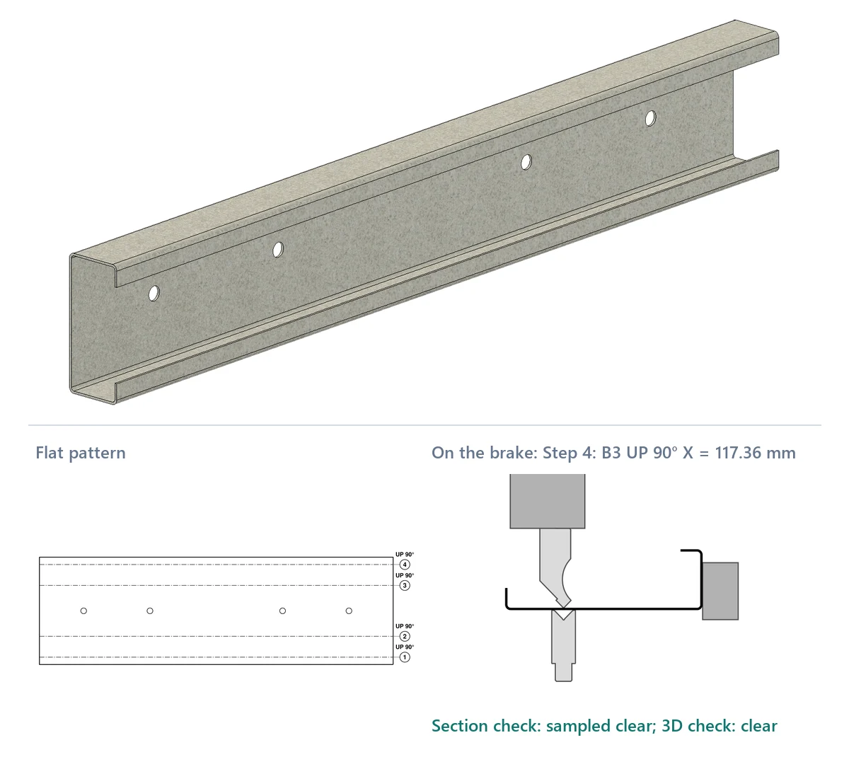
A galvanized lipped C channel in Fusion; under it the flat pattern with four numbered bends and step 4 from its bend sheet: the C on the die under the AMADA 604 straight punch

Lipped C channel

S235JR steel, 2 mm · 800 mm long · 4 bends

In the order drawn

Bent B1 to B4 with the UKB 11.151 punch the dialog started with, the third bend swings the flange and its lip into the punch and the upper beam at 82°. With that punch, none of the 24 bend orders clears the part, on either back-gauge side.

Auto tools + order

The search changes the punch to the AMADA 604 straight punch and its V16 die: both lips first, then the two flanges. 31 plans checked in 2.1 s, then the plan it keeps in 3D: every step clear.

Bend sheet (PDF)
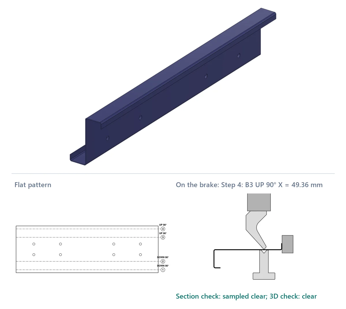
A blue Z section with lips in Fusion; under it the flat pattern with bends marked up and down, and step 4 from its bend sheet: the part on the die under the gooseneck, gauged on the formed lip

Z section with lips

S235JR steel, 2 mm · 800 mm long · 4 bends, two up and two down

In the order drawn

With the top lip bent last, the formed part meets the upper beam 2° into that bend.

Auto tools + order

The top lip first; the part is flipped over for the bottom lip and the first web bend, then flipped back for the last one. Both web bends are gauged on a formed lip, all four steps with the UKB 11.151. 4 plans checked in 1.3 s, then the plan in 3D: clear.

Bend sheet (PDF)
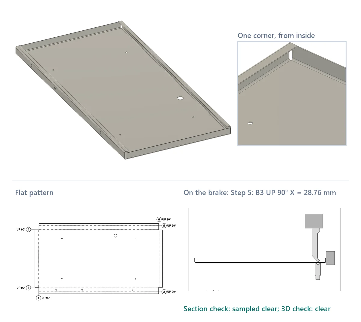
A grey cabinet door in Fusion with a close view of one corner from inside, showing a long wall with its return and the short flange; under it the flat pattern with six numbered bends and step 5 from its bend sheet

Cabinet door

S235JR steel, 1.5 mm · 400 × 832 mm · 6 bends, returns on the long edges

In the order drawn

The bottom flange is bent last, between the two long walls: they leave 400 mm for the punch, too short for the 415 mm and the 835 mm punch.

Auto tools + order

Top and bottom flanges first, then the returns, then the long walls between the flanges on an 830 mm AMADA station, 100L + 415 + 50 + 15 + 150 + 100R. With the 67 mm AMADA 604 there, the 3D check found the flange at B6 meeting the upper beam, so the search took the 120 mm AMADA 804: clear in the section check and in 3D. 67 plans checked in 10.7 s, two of them in 3D.

Bend sheet (PDF)

Bend Sheet

Plan the part in Fusion, hand one sheet to the operator

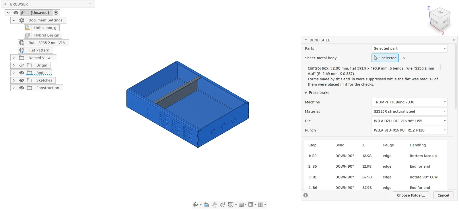
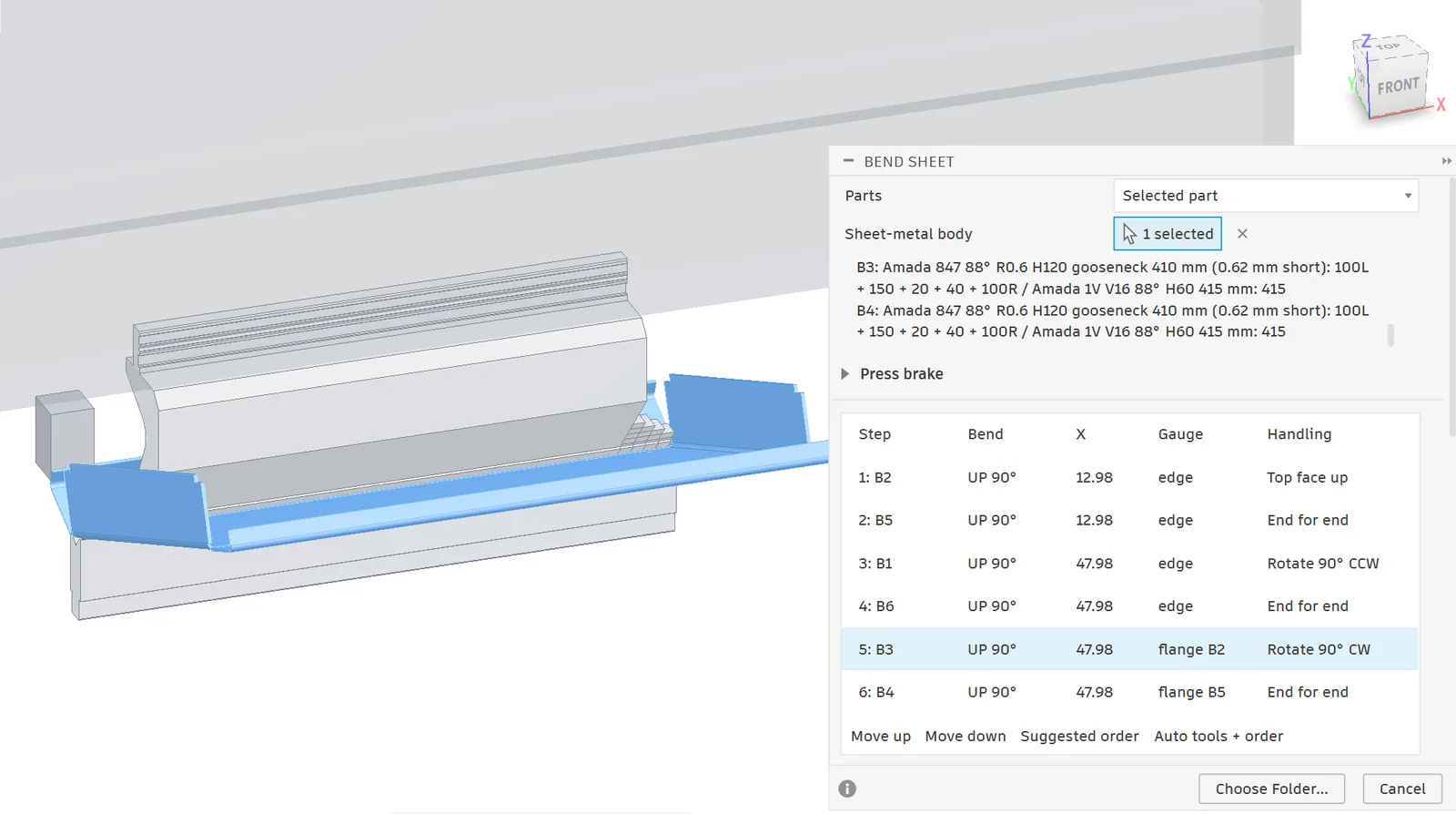
Run Bend Sheet on one part or on every sheet-metal part in the design. The dialog reads the flat pattern, takes the machine, material, die and punch saved with the part, and lists the steps with back-gauge X, gauge reference and handling. Move steps up or down, or let Auto tools + order find them; then write the files to a folder.

The Bend Sheet dialog in Autodesk Fusion next to the selected enclosure: part summary, press brake setup with machine, material, die and punch, and the bend order table with back-gauge X, gauge and handling
The Bend Sheet dialog next to the selected enclosure.

What the operator gets

  • ✓The setup: material, thickness, die, punch and machine.
  • ✓The flat pattern with numbered bends, each marked UP or DOWN, with the holes and slots of the blank.
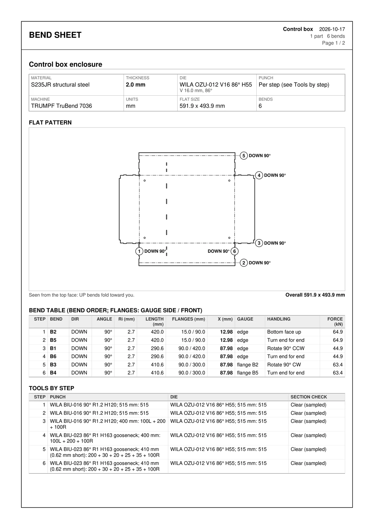
  • ✓The bend table in bend order: angle, inside radius, length, flanges, back-gauge X, what the part rests against (its edge or a formed flange), the handling and the force.
  • ✓The tools of every step with the station built from your pieces, the checks, and a side view of every step (below).
  • ✓A bend-program CSV with one row per step, and a flat DXF per part with CUT, BEND, ETCH and NOTES layers.

The sample is the enclosure above, planned with Auto tools + order for the TRUMPF TruBend 7036 of the starter library and its WILA tools. Over the 90 mm end walls a shorter punch meets the upper beam in 3D, so the search bends the returns first and the last three steps on the 163 mm gooseneck: every step is clear in the section check and in 3D. TRUMPF publishes no clamp or back-gauge finger for that machine, so the sheet lists the ones it assumes.

Page one of the enclosure's bend sheet: setup block, flat pattern with six numbered bends, bend table, tools by step and checks
Page one of the sample bend sheet.

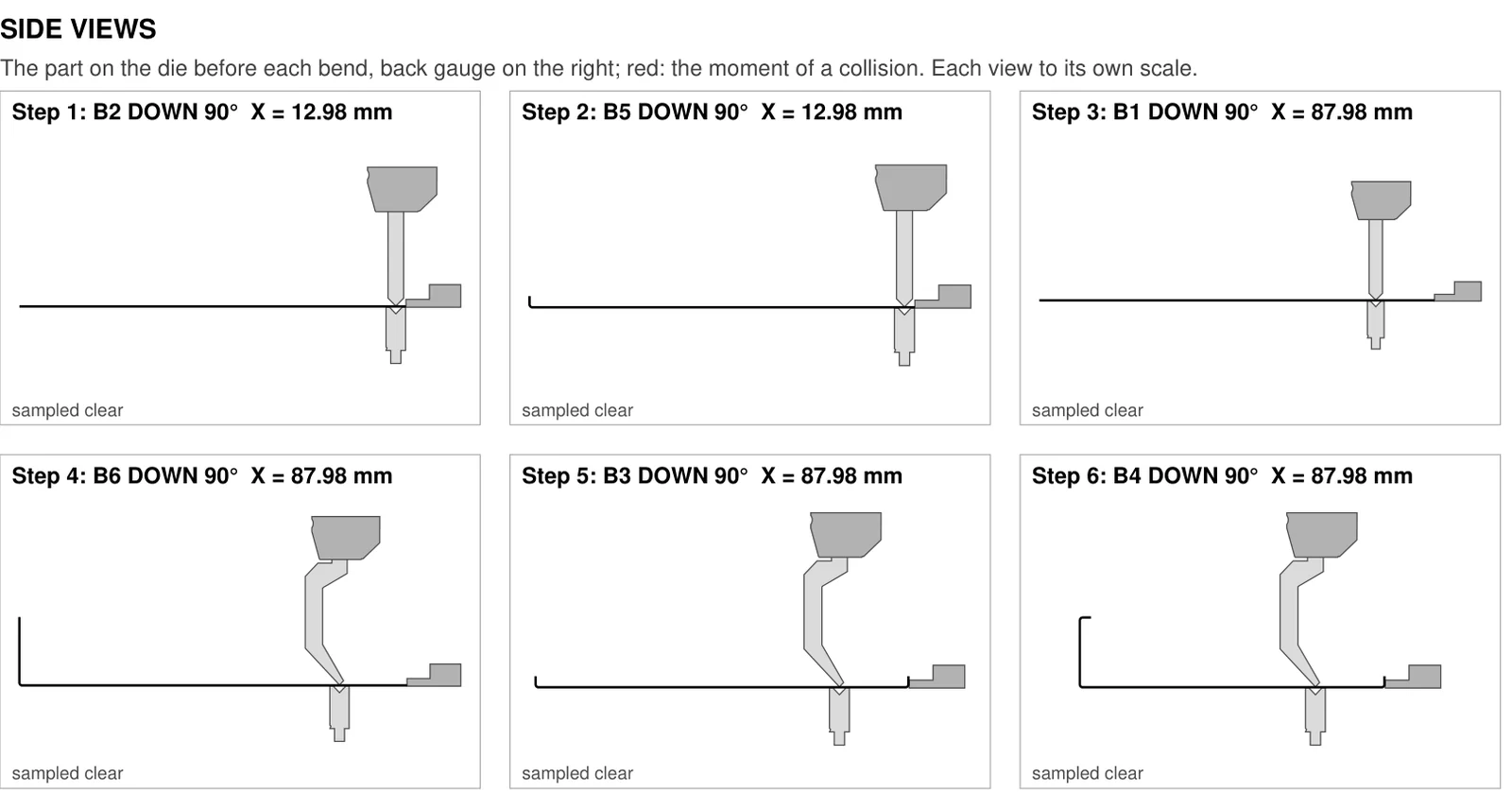
A side view of every step

The part on the die before each bend, cut across the bend line, with the earlier bends already formed and the back gauge on the right. Here the returns come first, then the end walls, then the long walls on the 163 mm gooseneck, gauged on their returns; they close over the end walls' corner tabs.

Six side views of the enclosure's bend sheet: the part on the die before each bend with a straight punch for the first three and the 163 mm gooseneck for the last three, the die, the upper beam and the back-gauge finger, each step marked sampled clear
Page two: the six steps of the enclosure.

The punch and die station of every step

Enter a punch or die as the sectioned set your shop owns, horns included. For each step, Bend Sheet builds the station the way press-brake controllers and offline programs do: it covers the bend line, short by at most the machine's tolerance (5 mm unless you set it), stops before the bends already formed across it, fills the room between the walls of a box, uses the fewest pieces elsewhere, and puts a horn at each end that faces a formed wall. The bend sheet, the CSV and the dialog name the pieces, and the 3D view and the 3D check model the horn's relief.

The Bend Sheet dialog in Autodesk Fusion with a 2 mm steel tray on the die at step 5, half way through the bend: the AMADA 847 gooseneck punch stands between the two end walls of the tray, its right horn relief beside the wall; the dialog lists the station of bends B3 and B4 as 410 mm, 0.62 mm short: 100L + 150 + 20 + 40 + 100R
Step 5 of the tray at mid-stroke: the 410 mm station between the end walls, and each step's pieces listed in the dialog.

A 50 mm deep tray, last two bends

A 420 × 300 × 50 mm tray in 2 mm steel with return flanges on its long walls, bent with the AMADA 847 gooseneck and a V16 die: the returns first, then the end walls, then the long walls between them. Their bend lines are 410.6 mm long, and the station is 410 mm: 100L + 150 + 20 + 40 + 100R, a horn at each end.

A punch or die with neither a length nor a set is taken as long as the bend line and listed under Assumed.

How a part is planned

Order, back gauge and handling

01

Suggested order

Outer flanges first, bends in the same direction grouped, short bends before long ones. Move any step up or down; the plan is recalculated at once.

02

Back-gauge X

Measured for every step on the side view of the part with the earlier bends formed: from the edge or from a formed flange, on the side with the shorter X that fits the back-gauge range.

03

Handling

Between steps the sheet says whether to flip the part over, turn it end for end or rotate it, with the angle and direction.

04

Saved with the part

Setup, order, tools and gauge sides are stored on the Fusion component, so the next bend sheet starts from them.

Checks

Problems found before the first hit

Besides the collision check, every step is checked against the setup. Errors and warnings are listed on the sheet with the step and the bend; checks that could not run, for example for lack of a tool rating, are listed as not checked.

Flange too short

A flange shorter than 0.7 × the die opening falls into the die. Checked on both sides of every step, with the earlier bends formed.

Angle, force and machine

A bend sharper than the die or punch angle needs acute tools. Force per metre is checked against the die and punch ratings, the total against the machine; the part length against the bed and X against the back-gauge range.

Holes and radius

A hole or cut-out closer to a bend line than 2.5 × thickness + radius is flagged, and so is an inside radius below the material minimum for that thickness.

Flat against the brake

When the flat uses another K-factor or radius than the chosen die and punch give, the sheet says so. Apply Bend Rule brings the flat in line.

Forms near a bend

A form made by the add-in that reaches into a bend zone is an error; one closer to where the bend starts than 3 t + R (Mate) is a warning. Every form rides on its flange through the section check, so a louver that rests on the die shoulders, hangs into the V or meets the punch is named in the result.

Sectioned and horn ratings

Makers can rate a sectioned punch or die lower than a solid one, and a horn lower still. When a step's station uses the pieces of a set or a horn, the force per metre is checked against those ratings where the maker publishes them.

Bend rules and test bends

A flat pattern that matches your brake

A flat is only right when its bend allowance matches the tooling that bends it. The add-in takes the radius and K-factor from the die you bend with, and from your own test bends when you have them.

Apply Bend Rule

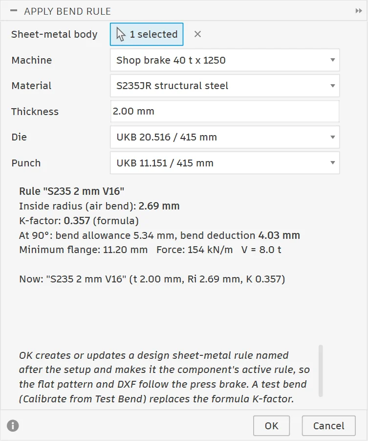
The inside radius of an air bend follows the die opening (or the punch radius, when that is larger) and the material; the K-factor follows DIN 6935. Apply Bend Rule shows the bend allowance, bend deduction, minimum flange and force, then writes the radius and K-factor into a Fusion sheet-metal rule named after the setup, for example S235 2 mm V16, and makes it the active rule of the part.

The Apply Bend Rule dialog in Fusion: machine, material, thickness, die and punch, and the resulting rule S235 2 mm V16 with inside radius 2.69 mm, K-factor 0.357, bend allowance, bend deduction, minimum flange and force
Apply Bend Rule for the enclosure.

Calibrate from Test Bend

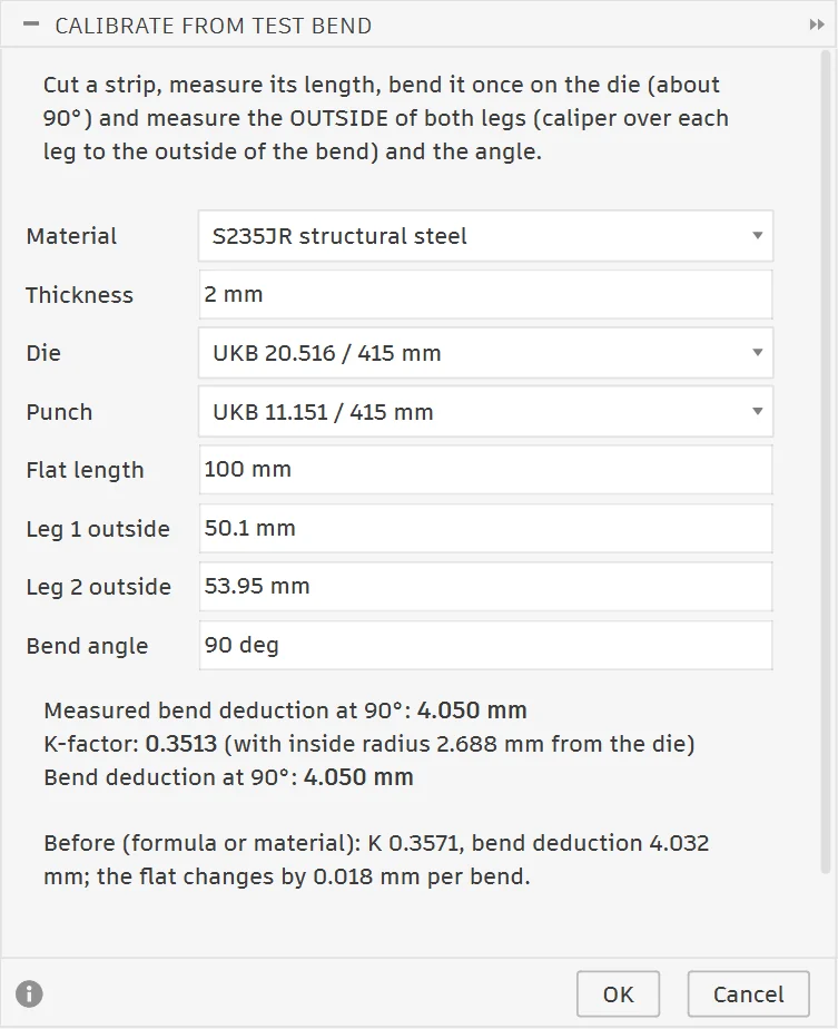
Bend one strip and measure its flat length, both outside legs and the angle. The add-in turns the measurement into the real bend deduction and K-factor, shows how much the flat changes per bend, and stores them for that material, thickness, die and punch. From then on that setup uses your numbers instead of the formula.

The Calibrate from Test Bend dialog in Fusion: material, thickness, die, punch, measured flat length and outside legs, and the measured bend deduction and K-factor compared with the formula
A test bend measured on the same die and punch.

Press Brake Library

Tooling data from real catalogues, every tool with its outline

The library starts with published values, each with its source, so a first bend sheet needs no typing. A value a maker does not publish is left empty, never guessed; the checks that need it say so.

  • ✓8 machines, including the Langmuir Titan 25T, TRUMPF TruBend 7036 and 5130, SafanDarley E-Brake 35, Bystronic Xpert Pro, Durma AD-R 30100, Amada HG-1003 and Harsle WE67K, each with its upper clamp and beam and a back-gauge finger.
  • ✓38 punches and 87 dies from AMADA, Wilson Tool, Langmuir Systems, WILA and UKB catalogues, with angle, radius, height, V opening and load rating where published, and an outline for every one: 37 punches and 70 dies from the makers' own drawings, the others from their published dimensions.
  • ✓Sectioned sets as the makers sell them: AMADA's 800 mm set with ears plus solid 835 and 415 mm pieces, WILA's /2 550 mm set with horns plus /1 515 mm pieces, Wilson Tool's X 35.875 in set with ears plus 36 and 18 in pieces, and the Langmuir Titan kits. Edit them to the pieces your shop owns.
  • ✓23 materials with tensile strength and the minimum bending radius by thickness, from EN 10025-2, ASTM A6, EN 10149-2, EN 485-2, SSAB and Outokumpu data.
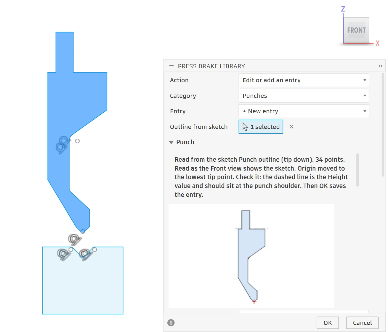
  • ✓Outline from sketch: draw a punch, die, upper beam or back-gauge finger in a Fusion sketch and click inside it. The outline is read as the Front view shows it, placed on the punch tip or the centre of the V, and drawn in the dialog at once.
  • ✓Import from DXF reads the same from a 2D drawing in mm or inches: centre lines, text and dimensions are skipped and arcs are kept within 0.005 mm. A tool with no drawing gets an outline drawn from its values: straight, gooseneck, acute and flattening punches; 1-V, acute, multi-V and hemming dies.
  • ✓Tooling systems: European (Promecam), American and New Standard (Wila/Trumpf). Tools are offered for the machines they fit.
  • ✓Your own machines, tools, materials and calibrations: add, edit, import and export as a JSON library.
Tool sources and CAD outlines
Autodesk Fusion in the Front view: a gooseneck punch drawn tip down in a sketch above a die sketch, the punch region selected; beside it the Press Brake Library dialog with Outline from sketch, 1 selected, the note that 34 points were read as the Front view shows the sketch with the origin moved to the lowest tip point, and the punch outline drawn in the dialog
Draw the punch in a sketch and click inside it: the library reads its outline, the origin on the tip.
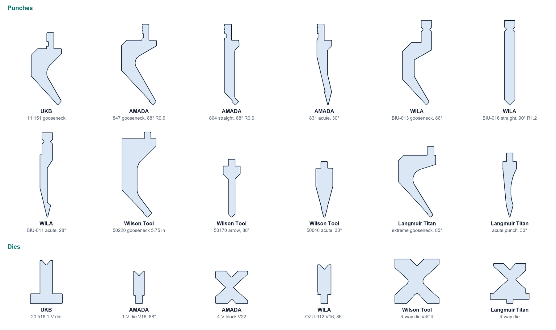
Twelve punch outlines and six die outlines from the starter library drawn to one scale: UKB, AMADA, WILA, Wilson Tool and Langmuir Titan gooseneck, straight, acute and arrow punches with their tangs, and 1-V dies, a 4-V block and 4-way dies
Some of the starter tools, drawn to one scale from their makers' drawings: the outlines the collision checks use.

Forms

Louvers, knockouts and beads, placed on the sheet

Louvers, lances, dimples, emboss and deboss forms, bridge forms, knockouts, extruded holes, reinforcing beads and gussets are created on a sheet face from presets or your own tools. Louvers, bridges and lances are modelled the way a lance-and-form tool makes them: the raised part is the sheet itself, one gauge thick, and every lanced edge stays open. Manufacturing Export writes their positions to a Punch Map and a shop plan for the punch press, checked hit by hit.

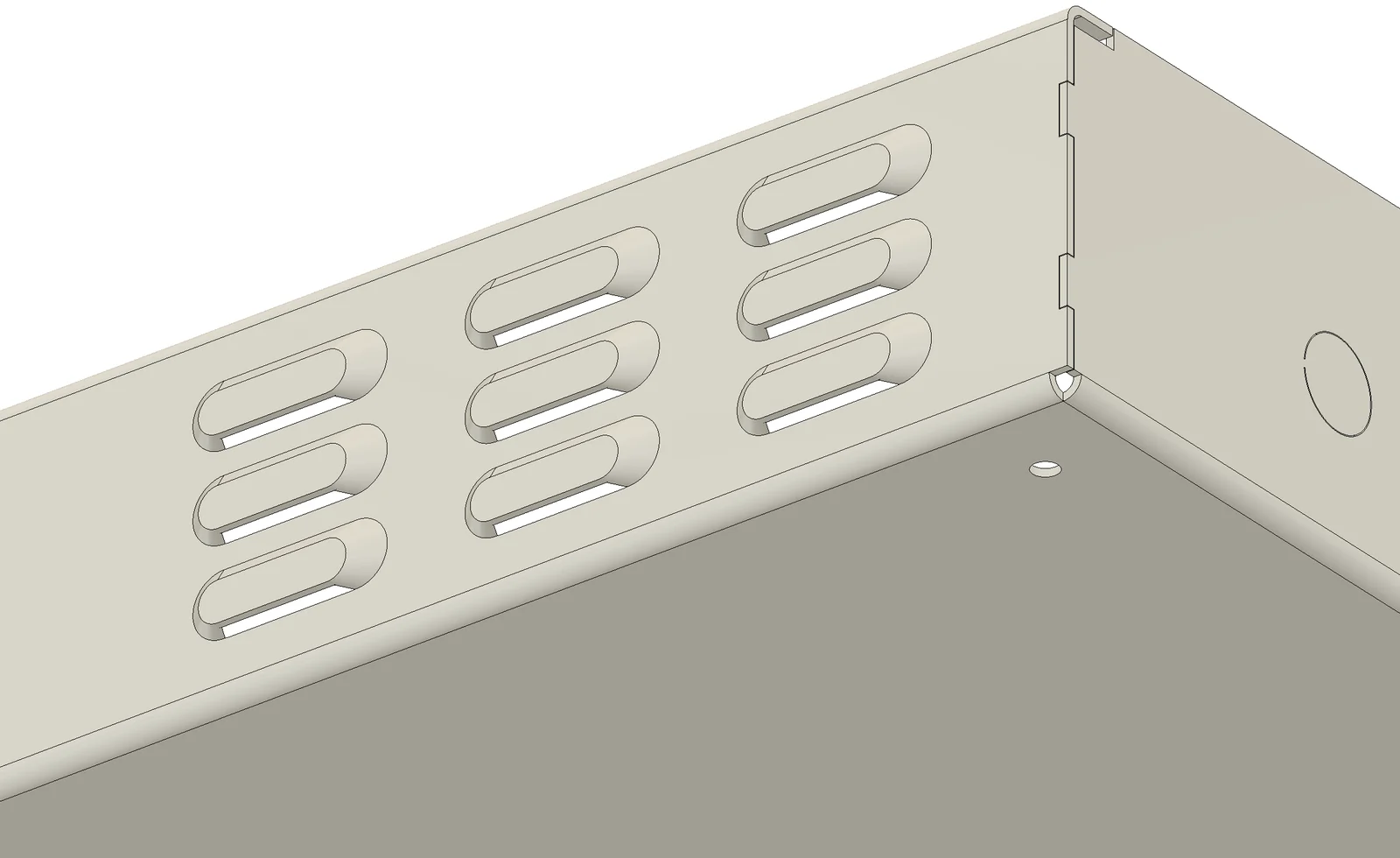
The front wall of the enclosure seen from below: three columns of three louvers, each a hood formed out of the wall with its open front facing down, and a cable knockout with break-out tabs in the end wall
Seen from below: nine louvers in the front wall, each open at the bottom where the sheet was lanced, and a cable knockout in the end wall.

Placed with a preview, kept with a record

  • ✓Pick the sheet face and the point; choose a preset or enter the dimensions of your own tool.
  • ✓Place one form, a row, a grid or a circle; Pattern Form also fills a sketched region with louvers around holes and keep-outs.
  • ✓The preview draws every outline on the face before anything is created, and Show the forming tool adds the punch and die of the form in 3D on a flat face (the first form of a pattern): where the tool shears the sheet, the punch edge stands on the cut line and the die edge one cutting clearance outside it. Stroke closes the tool from open to the bottom of its stroke, in Create Form and in Edit Form.
  • ✓Louvers, bridges and lances are checked against the sheet: at least 1.5 thicknesses high, with a warning when a form is higher than four thicknesses or a louver is less than twice as wide as it is high.
  • ✓Each form stores its tool, position, orientation and checks, and Edit Form rebuilds it.
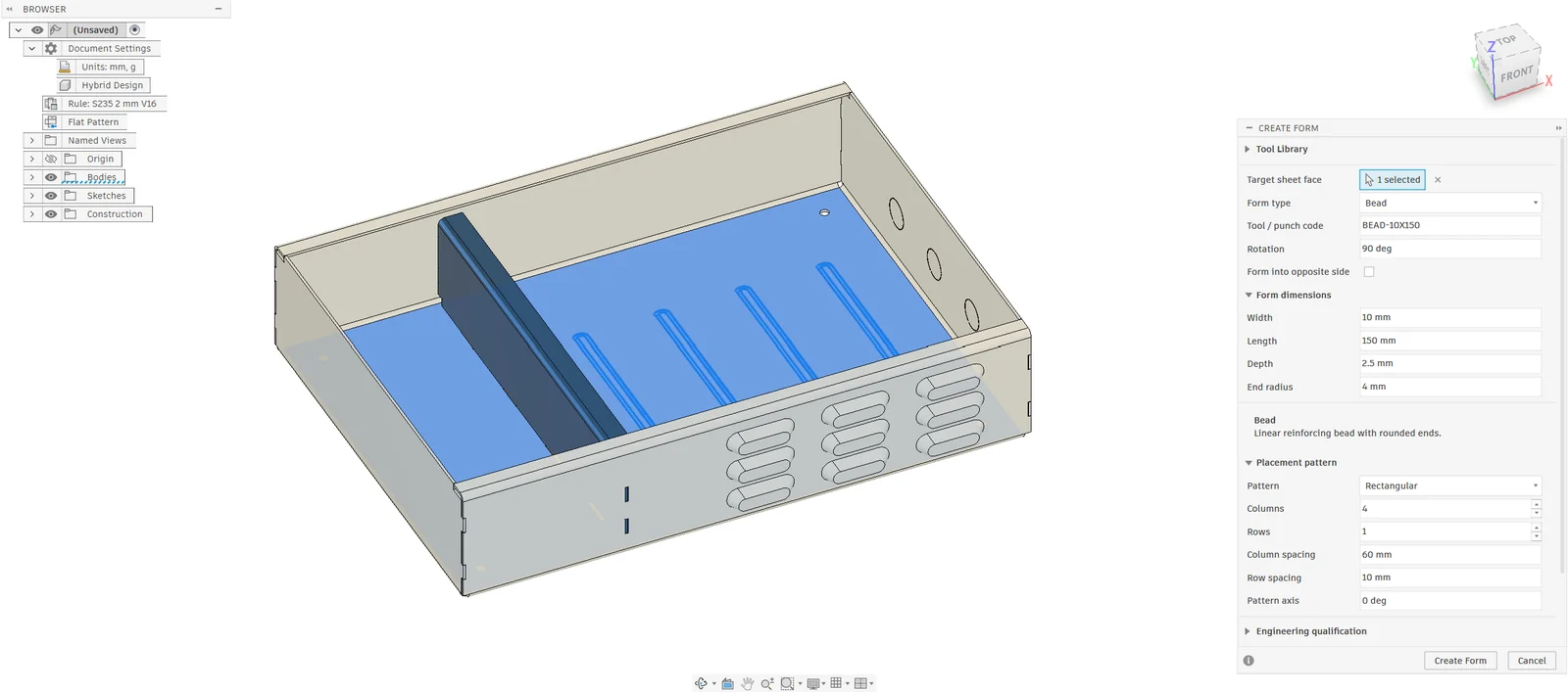
The Create Form dialog in Fusion with Bead selected, its width, length, depth and end radius, a rectangular placement pattern, and the preview of four beads on the base of the enclosure
Create Form: a row of four stiffening beads previewed on the base of the enclosure before they are created.
Stroke from 0 to 100 % on a louver: the die above comes down onto the sheet and the punch below rises into the louver, standing inside it at the bottom of the stroke.

Checked against the tool makers' limits as you edit

The Checks box under the form's description shows what the tool makers publish for that form while you place it: Mate, AMADA, Conic, TRUMPF, Wilson Tool, NEMA and Protocase. It covers the height against the sheet thickness, wall and forming angles, pre-holes and ties, and the distance to sheet edges and cut-outs (3 t), to other forms (6 t, louvers 3 t) and to where a bend starts (3 t + R).

They are warnings, not blocks: a shop with other tooling may still make the form. The result lists them again, Audit Forms measures them again before release, and the Punch Map keeps them with the form.

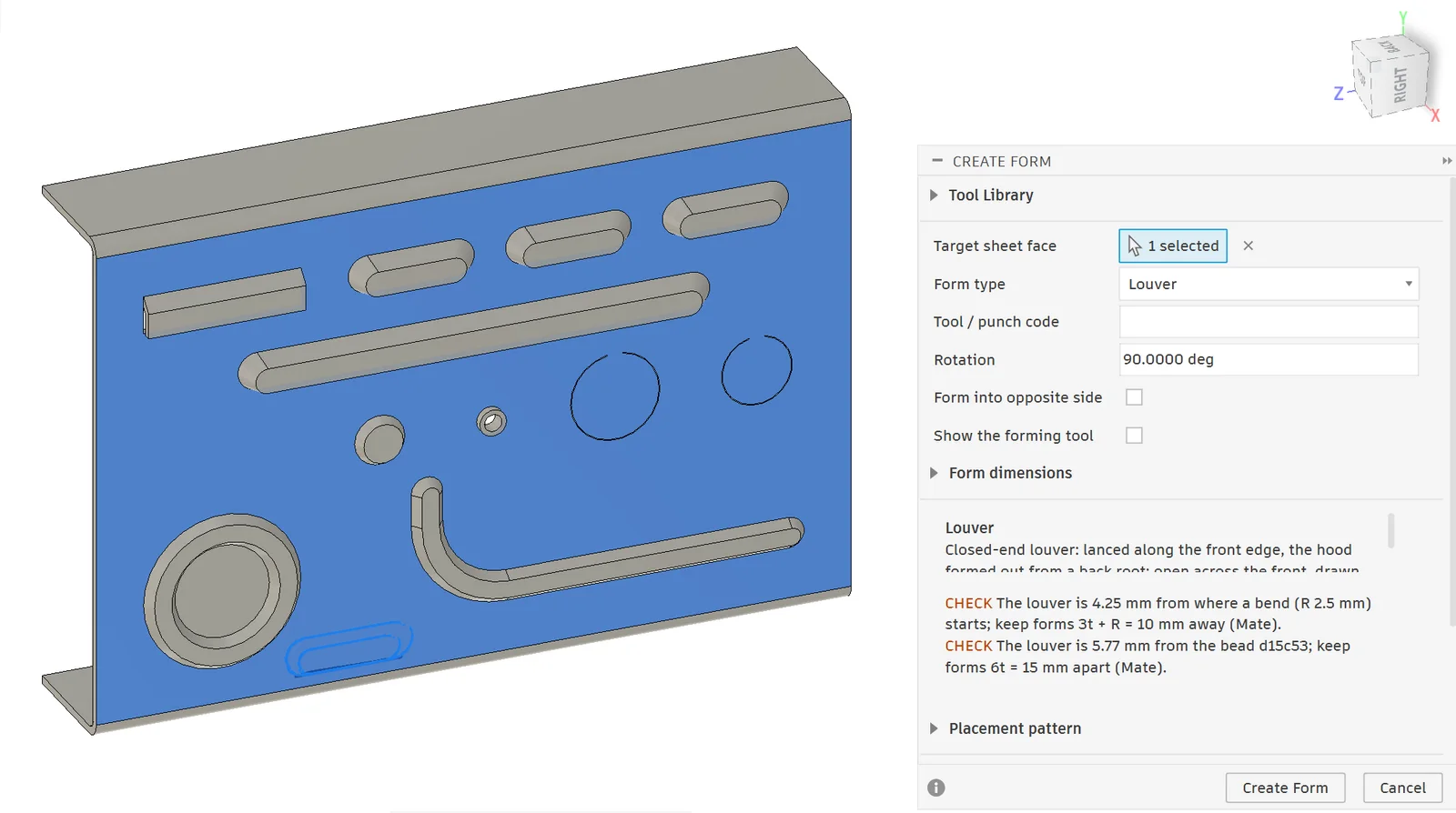
The Create Form dialog in Autodesk Fusion placing a louver near the lower bend of a 2.5 mm U channel; the Checks box warns that the louver is 4.25 mm from where the bend starts, keep forms 3t + R = 10 mm away (Mate), and 5.77 mm from a bead, keep forms 6t = 15 mm apart (Mate). The channel carries an open-end louver, closed louvers, a progressive louver, two knockouts, an M6 thread extrusion, a dimple and two beads along sketch paths
A louver placed too close to a bend and to a bead: the Checks box gives Mate's minimum distances before the form is created.

Made the way shops make them

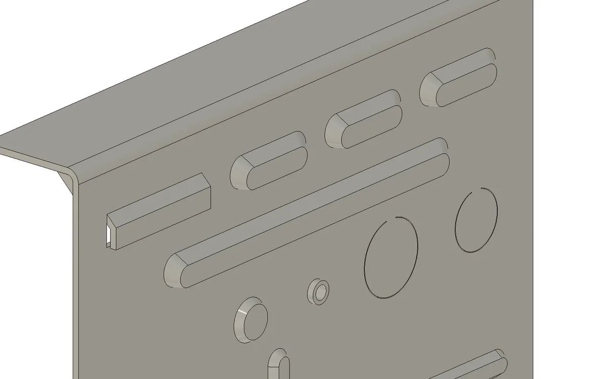
Close view of a 2.5 mm steel panel: an open-end louver made in a press-brake die, three closed louvers, a long progressive louver, two knockouts with their ties, an M6 thread extrusion and a dimple
An open-end louver from a press-brake die (left), closed louvers, a 150 mm progressive louver, NEMA knockouts, an M6 thread extrusion and a dimple.
  • ✓Louvers with closed or open ends, made in one hit, progressively for any length (from the middle out), or in a press-brake louver die from a slit cut beforehand; the slit goes on the CUT layer.
  • ✓Knockouts by NEMA trade size: the hole, the ties and the cut gap are filled in for the sheet.
  • ✓Extruded holes for threads: choose the thread and the tap, forming or cutting, and the bore, pre-hole and collar are filled in from Mate's table. The model has no thread.
  • ✓Beads made in one hit, nibbled, rolled by a wheel tool or pressed by a press-brake rib die. Nibbled and rolled beads follow a sketch path of lines and arcs, and a closed path makes a ring; a rolled path is checked against the wheel tool's smallest radius.
  • ✓Gussets across a bend: a stiffening rib pressed into the inside of the bend in the bend stroke. The rib is its own body, so the sheet and its flat pattern stay as they are, and Bend Sheet warns that its bend needs gusset tooling.

A shop plan for the punch press

Manufacturing Export turns the forms into a plan for the turret. Choose which face of the blank is loaded up, or Auto, which puts most forms up: makers form up whenever they can and form down last. The PDF, the CUT/FORM DXF, the SVG and the Punch Map then give every form as it is loaded.

  • ✓Each form UP or DOWN with its height, from the sheet face it rises from to its top.
  • ✓The hit order: cuts first, then the forms up, then the forms down, one tool at a time; Avoid crushing, the default, can move a hit earlier (see the checks below).
  • ✓Auto-index stations: a form at any angle other than 0, 90, 180 or 270° is marked for one.
  • ✓Pre-holes of extruded holes and slits of press-brake louvers on CUT; tool centres and headings on FORM_UP and FORM_DOWN. The sheets say not to mirror the blank: the forms are directional.
  • ✓Forms that are not qualified for production give a reference package marked do not manufacture, never a production DXF.
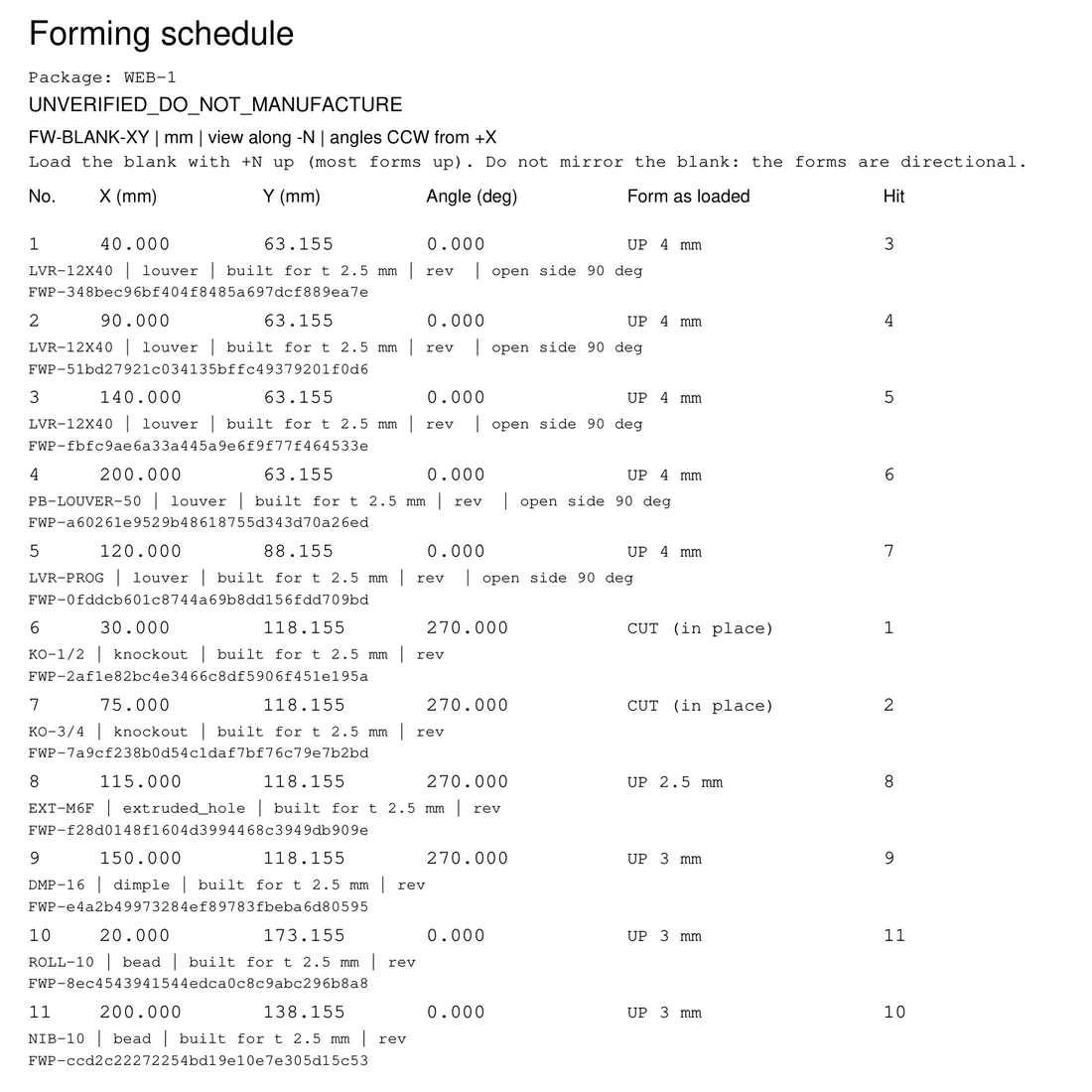
Forming schedule of the test panel from its handoff PDF, marked unverified, do not manufacture: the blank loaded with +N up, and for each form its X and Y, angle, the form as loaded (UP 4 mm for the louvers, CUT in place for the two knockouts, UP 2.5 mm for the M6 extrusion, UP 3 mm for the dimple and the beads) and its hit number, the knockouts first
The forming schedule of the test panel. Its presets are not qualified, so the package is marked do not manufacture.

The punch-press job, checked hit by hit

On a turret punch press the stripper holds the sheet on the die through every stroke, so a later hit can press flat a form made before it. Manufacturing Export checks the job in its hit order, with the station sizes you choose, and lists what it finds on a Punch-press checks page of the shop PDF, in the SVG and, form by form, in the Punch Map. The checks are warnings: nothing is blocked.

The job of a test blank, hit by hit in its plan's own order: each tool closes in its station, and at hit 5 the louver's D-station stripper lands on the dimple made at hit 3, so both turn red.
  • ✓A station for every tool: each one-hit tool gets the smallest station that takes it, on a thick turret (stations A to E, or with an F station) or with TRUMPF tool sizes, and a tool larger than the largest station is flagged.
  • ✓Forms under a later hit: a form made up that lies under the stripper of a later hit, or a form made down over a later hit's die.
  • ✓The clamps: forms in the clamps' dead zone (orange in the 3D view), 72 mm from the clamped edge by default, along the whole edge or beside the clamp positions you enter.
  • ✓Hit order: Avoid crushing, the default, makes a hit before the form its tool would land on, within the forms made up and within those made down, where such an order exists. Because forms made down come last, a form-down hit that lands on a form made up is only flagged. The plan's own order is kept on request.
  • ✓Show the job in 3D draws the job beside the model: the blank as loaded, the forms made so far, the hit's forming tool between its station's stripper above and die below, and the clamps' dead zone. Hit steps through the job and Stroke closes the tool.
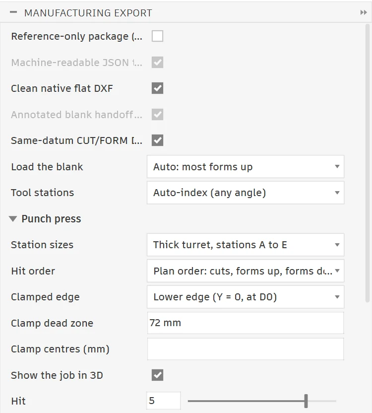
The Manufacturing Export dialog in Autodesk Fusion: the CSV, JSON, DXF and handoff options, Load the blank Auto, Tool stations Auto-index, and the Punch press group open with Station sizes Thick turret, stations A to E; Hit order Plan order; Clamped edge Lower edge (Y = 0, at D0); Clamp dead zone 72 mm; no clamp centres; Show the job in 3D ticked and Hit 5
The settings behind the clip: a thick turret with stations A to E, Hit order Plan order, the lower edge clamped with a 72 mm dead zone, and Show the job in 3D at hit 5. With Avoid crushing, the default, the louver is made before that dimple.
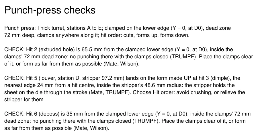
The Punch-press checks page of the shop PDF for the same blank: the setup line (thick turret, stations A to E; clamped on the lower edge, dead zone 72 mm deep; hit order cuts, forms up, forms down) and three checks: the extruded hole at hit 2 and the deboss at hit 6 inside the clamps' dead zone, and the louver at hit 5, station D with a 97.2 mm stripper, landing on the dimple made up at hit 3, whose nearest edge is 24 mm from the louver's hit centre, inside the stripper's 48.6 mm radius
The same job on the Punch-press checks page of the shop PDF: the distance for every finding, and the station and stripper size where a hit lands on a form.

Tab and Slot

Parts that locate themselves before welding

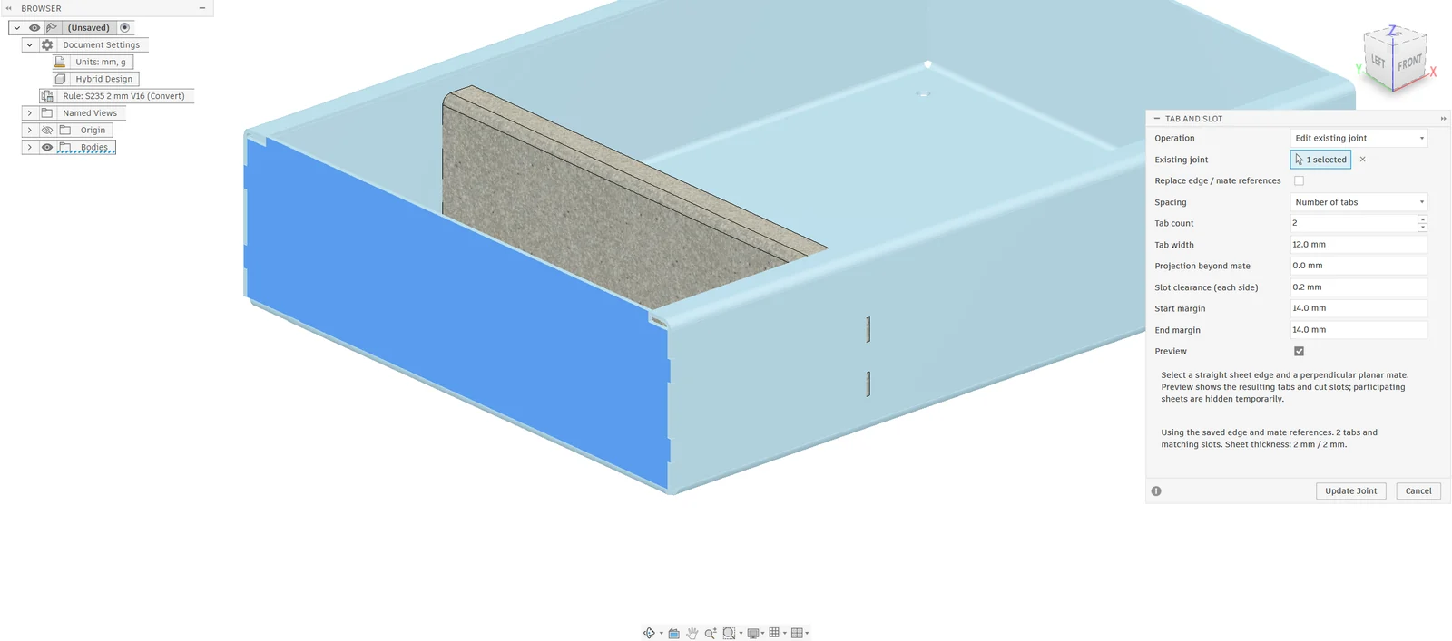
Tab and Slot adds locating tabs to the edge of one sheet and cuts matching slots, with clearance, in the sheet it meets at 90°: by count or by pitch, with margins at both ends, up to 50 tabs. The preview shows the tabs and the cut slots before anything is created, and the joint stays editable while it is the last one in the timeline. The two walls can be separate bodies or one folded part. In the enclosure, the mounting plate sits in four slots in the base and two in each long wall.

The enclosure with its blue mounting plate lifted out: the tabs along the bottom and both ends of the plate, and the matching slots in the base, the back wall and the front wall
The mounting plate lifted out of the enclosure: its tabs and the slots they fit.
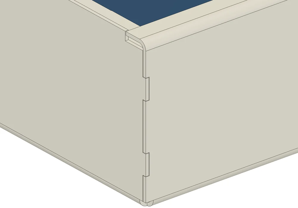
A closed corner of the enclosure: two tabs on the end wall pass through slots at the end of the long wall, flush with its face, under the return flange
A closed corner: two tabs on the end wall lock it through the end of the long wall.

Tabs are cut as part of the blank: create the joints before the forms, so the slots stay in the flat pattern and in the DXF. The sheets are native Fusion sheet-metal bodies of one component.

The Tab and Slot dialog in Fusion editing a corner joint of the enclosure: tab count, tab width, projection, slot clearance and margins, with the preview of the tabs on the end wall and the slots at the end of the long wall
Tab and Slot editing a corner joint: tab count, tab width, projection, slot clearance and margins, with the preview.

Eleven commands

In the Sheet Metal tab, panel Press Brake

The most used commands sit on the ribbon; the panel menu holds all eleven.

The Sheet Metal tab of the Fusion Design workspace with the Press Brake panel at its right end
Bend Sheet tool illustration

Bend Sheet

Plans the bends of a part, step by step, and writes the bend sheet PDF, the bend-program CSV and a flat DXF.

Apply Bend Rule tool illustration

Apply Bend Rule

The radius and K-factor of your material, die and punch, as a Fusion sheet-metal rule.

Calibrate from Test Bend tool illustration

Calibrate from Test Bend

Bend deduction and K-factor from one measured test strip.

Press Brake Library tool illustration

Press Brake Library

Machines, punches, dies, materials and calibrations, every tool and machine with its outline, with JSON import and export.

Create Form tool illustration

Create Form

A form on a sheet face from a preset or your own tool, with a live preview and the tool makers’ limits checked as you edit.

Edit Form tool illustration

Edit Form

Change a saved form and rebuild its geometry, or move it to a new centre on the same sheet.

Pattern Form tool illustration

Pattern Form

Rectangular and circular patterns of a form, or louvers filling a sketched region.

Tab and Slot tool illustration

Tab and Slot

Locating tabs and matching slots where two sheet-metal walls meet at 90°.

Manufacturing Export tool illustration

Manufacturing Export

Punch Map CSV with the form positions, the punch-press shop plan checked hit by hit, optional JSON, an annotated blank handoff and the native flat DXF.

Audit Forms tool illustration

Audit Forms

Check the saved forms, their references and the model state before you release the part.

About Sheet Metal and Press Brake tool illustration

About Sheet Metal and Press Brake

Help, version, license status and support.

Sheet Metal & Press Brake v1.0.0 · Windows · Early access

Plan your next part for the brake

US$49/year or US$8/month per user. Email us for the current build, payment and installation. The 3-day trial starts with the first protected command you run.

Read the guide first

The user guide covers each command, the library format, the checks and what the add-in does not check.

Before you start

Sheet Metal & Press Brake FAQ

Does it change the Fusion flat pattern?

It reads it. Bend Sheet takes the bends, angles and radii from Fusion’s own flat pattern and never redraws it; forms made by the add-in are suppressed while the flat is read and restored afterwards. Apply Bend Rule only sets the sheet-metal rule (inside radius and K-factor) of the part, so that Fusion’s flat and its DXF match what your brake produces.

How does this compare to Inventor Bend Order or offline press-brake CAM?

Autodesk Inventor can number bend order on a flat pattern, and standalone offline press-brake CAM programs machine-specific controller code on a separate PC. Sheet Metal & Press Brake plans a collision-checked bend order, with its punch and die, back-gauge X and handling, inside Autodesk Fusion on your own sheet-metal model and tooling, and exports an operator setup sheet PDF, a bend-program CSV and a layered flat DXF, not controller code. See the comparison table

Which parts can it read?

Fusion sheet-metal parts, one part or every sheet-metal part in the design. When a part has no flat pattern yet, one is created from its largest flat face. Bends up and down at any angle are planned; a bend closed past 170° is listed as a hem, which needs a hemming die or a flattening step.

Do I need my own tool data first?

No. The starter library has published catalogue values for eight machines, 38 punches, 87 dies and 23 materials, and every punch and die has an outline for the collision checks, so a bend sheet works at once. A tool of your own can be added from a Fusion sketch, a DXF, or the height, width, angle and gooseneck depth you enter. See the Press Brake Library

Is the collision check a machine simulation?

No. The section check sweeps a 2D section of the part through each air bend with the punch, die, back-gauge and beam outlines, on every plan; Check all steps in 3D folds the real part from its flat and tests every step against the punch, die and beam as solids. Neither one models springback, tool or machine deflection or the side frames of the machine. Every assumption is listed with the result, and whatever could not be checked keeps the step incomplete instead of clear. Try unusual parts on the machine. See the current limitations

Does it choose the punch and die for me?

Yes. Auto tools + order starts with the punch and die you chose, then tries the other compatible tools of your library, both back-gauge sides and other bend orders, and checks the plan it finds in 3D before it keeps it. You can always set the order and the tools by hand. See Auto tools + order

Does it know the sectioned punches and dies my shop owns?

Yes. Enter a punch or die as the pieces you have: AMADA’s 800 mm set reads 100L, 10, 2x15, 20, 40, 50, 150, 300, 100R, and *x835 adds as many solid 835 mm pieces as needed. For every step, Bend Sheet builds the station from those pieces, with a horn at each end that faces a formed wall, and writes it on the bend sheet and in the CSV. The starter AMADA, WILA, Wilson Tool and Langmuir Titan tools come with the sets their makers publish. See how a station is built

Does it work with inch designs?

Yes. Lengths and the back-gauge X follow the design units, with three decimals in inches. For an inch design, American tooling and ASTM materials are offered first.

What is in the bend-program CSV?

One row per step: part, step, bend, angle, direction, die, punch, back-gauge X, gauge reference, handling, force and the problems found. Type it into the controller or keep it with the job. It is not a program file for a specific CNC controller.

Are the forms native Fusion forming tools?

No. A form is modelled geometry with a saved manufacturing record, and while you edit it Create Form shows the tool makers’ published limits for it as warnings. The supplied form presets are reference examples until you qualify your own tool. See the form checks

Does it check the punch-press job?

Yes, as warnings. Manufacturing Export checks the job in its hit order: the station of every one-hit tool, a form made up under the stripper of a later hit or a form made down over a later hit’s die, and forms in the clamps’ dead zone. Show the job in 3D steps through the hits beside the model. See the punch-press checks

Is there a free trial, and which systems are supported?

There is a 3-day trial that starts the first time you run a protected command while signed in and online; opening About alone does not start it. This release is for Fusion on Windows.

How do I get Sheet Metal & Press Brake?

It is in early access: email support@vanthanbk.com for the current build, installation and payment. Pricing is US$49/year or US$8/month per user.

Supported scope

Current limitations

Check these before you rely on a result.

Section and 3D checks

The section check sees one sampled section through each bend; Check all steps in 3D adds the real part against the punch, die and beam when you run it. Hems, springback, tool and machine deflection and the side frames of the machine are not simulated; hems are reported as incomplete.

The clamp and back gauge of your machine

Machine makers rarely publish their back-gauge fingers, and some publish no clamp: those starter machines take the clamp of an equivalent maker and a typical two-step finger, listed under Assumed. Enter, sketch or import the outlines of your own beam and back gauge where they differ.

A bounded tool search

Auto tools + order stops after eight seconds. With a large library it can stop before it finds a complete plan; set the order and tools by hand, or keep only the tools of your machine in the library.

One K-factor per part

Each bend radius is read from the flat with the K-factor of the part's rule. Check bends that have their own unfold settings in Fusion.

Forms and joints in one component

Forms are made on the sheet that owns the component's flat pattern; strain, thinning and springback are not calculated. The tool makers' limits are published values, not a qualification of your tools. Tab and Slot joins straight 90° edges of sheets in the same component. The punch-press checks take every tool as a disc of its station's stripper and die, and the blank as the sheet that is clamped: check tools relieved for nearby forms, and parts nested in a larger sheet, yourself.

Windows only

This release runs in Fusion on Windows. macOS is not included yet.

Read the detailed limits

More for Autodesk Fusion (Fusion 360)

Combine with other VanThanBK fabrication & assembly add-ins

Compare all 6 add-ins →
Steel Frame & Weldments Pro

Tube folding, welds and frame analysis in Fusion

Tube & Pipe Routing

From tube routes to fabrication packages

Hole Series & Fasteners

Matching holes and bolts in every part

Auto Backup & Export

Local backups of your Fusion cloud designs