01
Pick centres and parts
Run Hole Series in your Hybrid assembly. Select sketch points, vertices, circular edges or the face of a part that already has holes as centres, then the parts to drill, or let it find the parts on the hole axis.
Autodesk Fusion add-in · v1.0.1 · Windows

Matching holes in every part, with the bolts.
Change it once, everything follows.
Pick the hole centres, or the face of a motor or rail, and the parts to bolt together. Each part gets the right hole for its side (clearance, tapped, counterbore, countersink, a nut pocket or a slot), and the screws, washers and nuts come with a length that fits. Change M8 to M10 later and the holes and the hardware change in every part, also when the parts are separate linked Fusion files.
Then US$49/year or US$8/month per user · Windows
Next to Fusion's Insert Fastener, Edit in Place & other CAD
Fusion's Insert Fastener places a screw, nut or washer from its library into a hole that is already modelled. Unlike SolidWorks Hole Series or Inventor Bolted Connection, native Fusion leaves the hole-making to you: sketching or projecting holes across parts with Edit in Place or Insert Derive, setting the right hole type on each side, and doing it all again when M8 becomes M10. Hole Series & Fasteners does that work.
| Job | Fusion on its own | With Hole Series & Fasteners |
|---|---|---|
| Holes through every part of a joint | Fusion on its ownSketch and cut the hole in each part, with the right type for each side | With Hole Series & FastenersOne Hole Series: clearance, tapped, counterbore, countersink, nut pocket or slot, each part on its side |
| Screws, washers and nuts | Fusion on its ownInsert Fastener or McMaster-Carr into the existing holes: size from the hole, length from the list or Auto | With Hole Series & FastenersAdded with the holes; the length is picked from the measured stack and the thread engagement you ask for |
| Change M8 to M10 | Fusion on its ownChange each hole, then each fastener | With Hole Series & FastenersOne edit: holes and hardware change in every part |
| A motor or rail with its own holes | Fusion on its ownMeasure or project its hole pattern into your part | With Hole Series & FastenersPick its face: its holes become the centres and the size is read from them |
| External linked part files (xrefs) | Fusion on its ownOpen, change and save each file, or use Edit in Place / Insert Derive one at a time | With Hole Series & FastenersEach file is drilled and saved for you, also inside linked subassemblies |
| Ordering and the shop | Fusion on its ownParts lists and hole notes in the drawings | With Hole Series & FastenersStraight from the assembly: a hardware list with order designations and search links, and a hole chart per part |
Insert Fastener remains the right tool when every hole already exists; its library also has rivets. Hole Series & Fasteners is for the joints whose holes still have to be made, matched across the parts and kept in step.
What it does
Jobs 1 to 3 follow one drive mount before and after each step; jobs 4 and 5 use other assemblies. In each, the parts are separate Fusion files linked into the assembly, and every picture is a real run. Components of one design work the same way, without the file saves.
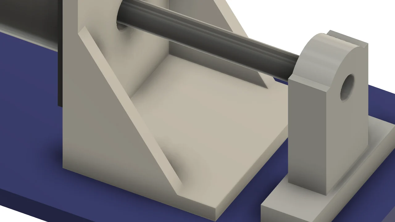
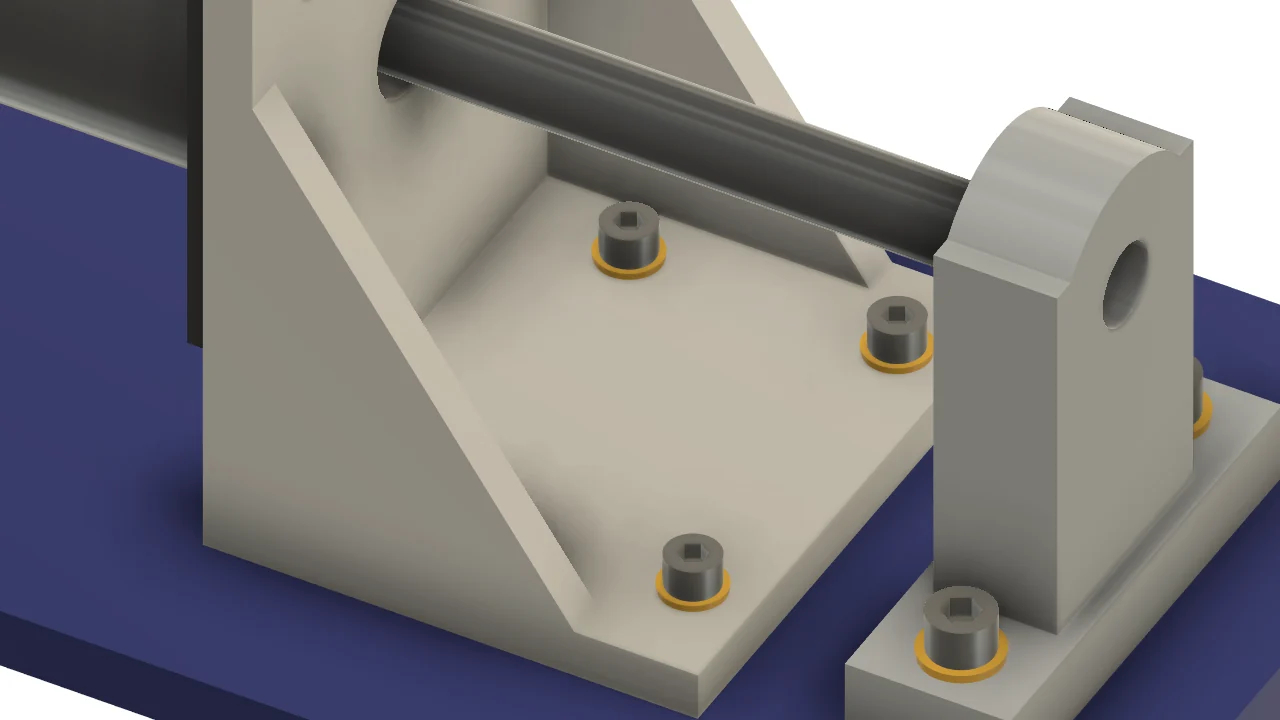
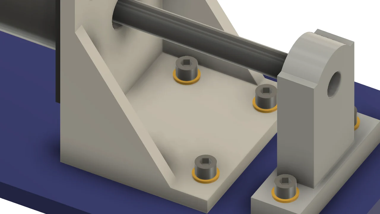
Pick the centres once in the assembly. Hole Series & Fasteners drills the bracket and the base plate, each in its own file with the right hole for its side: clearance in the bracket, M8 tapped in the plate. Both files are saved and the assembly is updated.
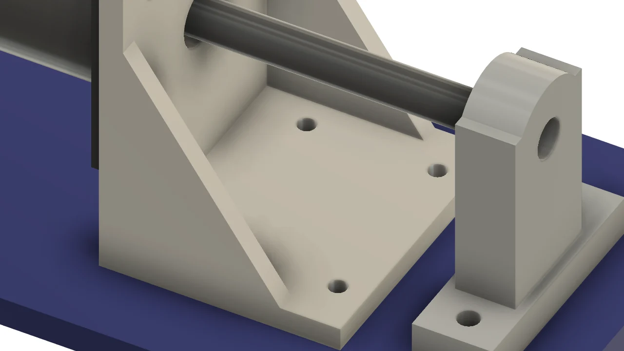
Tick Add fasteners and the joint gets its screws, washers and nuts.
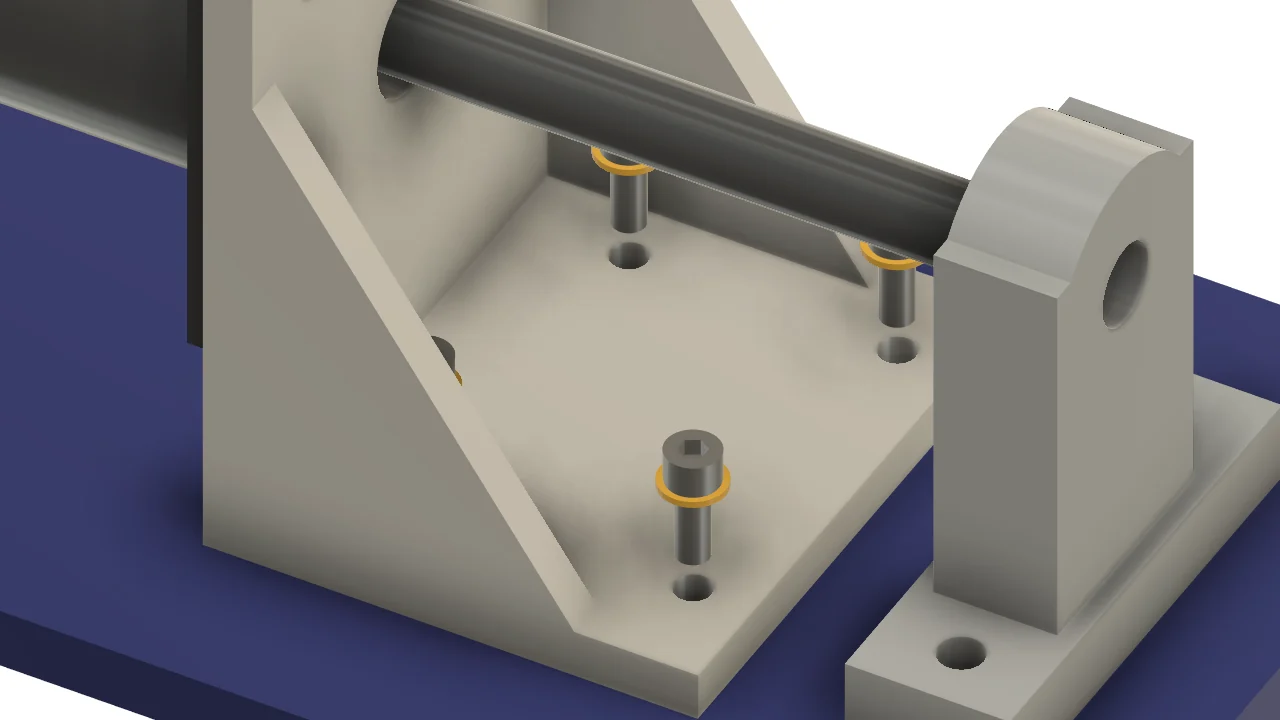
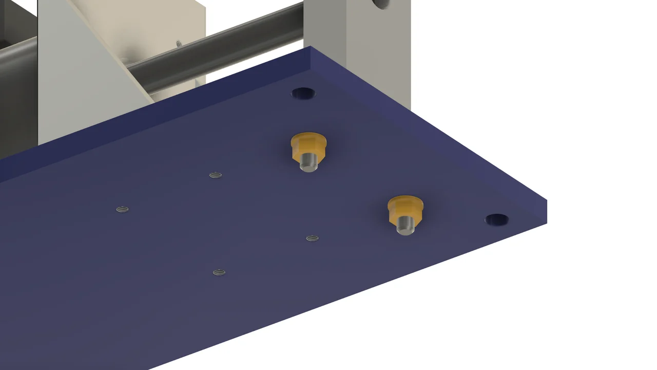
Open the joint again with Edit Assembly Feature and change M8 to M10. Hole Series & Fasteners makes the bracket holes bigger, re-taps the base plate for M10, saves both files and swaps the screws and washers.
Another assembly: a sensor bracket bolted to a machine upright, both separate Fusion files. The screw centres come from the bracket itself, two layout points in its own file. The bracket is moved 40 mm up, and the screws no longer line up. Update All measures the joint again, drills the upright and the bracket at the new height, saves both files and moves the screws with them.
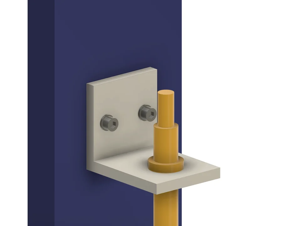
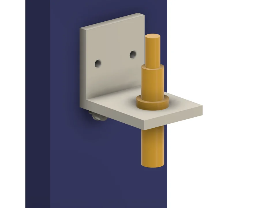
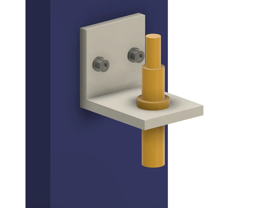
Not sure what moved? Audit Assembly checks every joint first and changes nothing. After the move above it marks the Hole Series and its screws [CHANGED]: the bracket, one of the drilled parts and the owner of both centre points, has moved. Update All is the next step.
Hole Series & Fasteners audit
Objects: 2 | Healthy: 0 | Changed: 2 | Errors: 0 | Orphans: 0

[CHANGED] Fastener Stack 1 (Managed by Hole Series 1 - Read Only)
- INFO: Target 1 occurrence has moved.
- INFO: Placement 1 occurrence has moved.
- INFO: Placement 2 occurrence has moved.

[CHANGED] Hole Series 1
- INFO: Target 1 occurrence has moved.
- INFO: Placement 1 occurrence has moved.
- INFO: Placement 2 occurrence has moved.
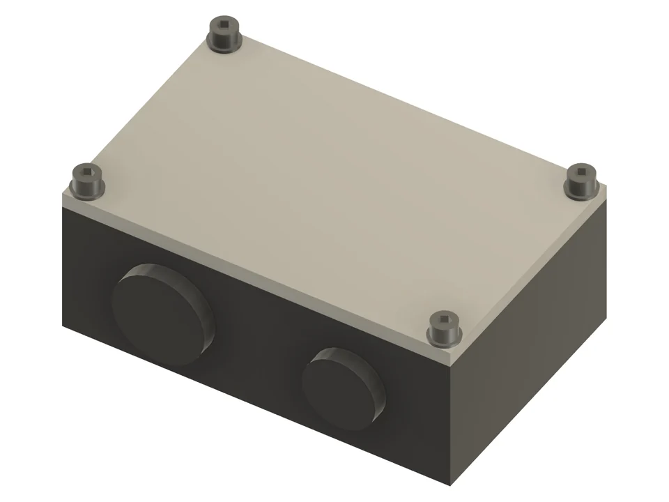
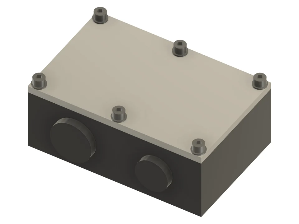
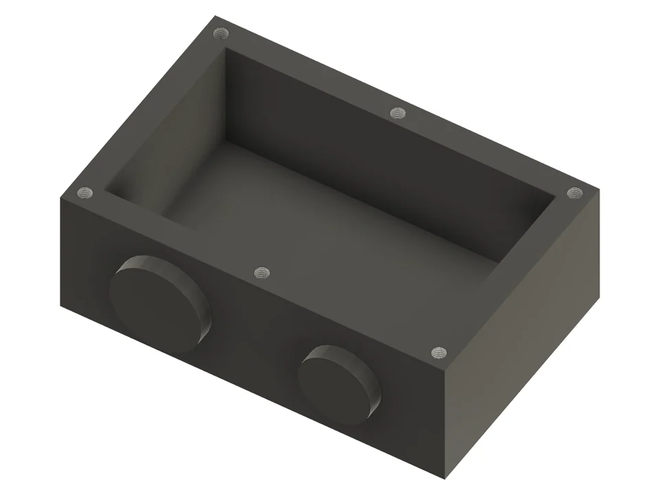
A cover screwed onto a gear housing, again two separate Fusion files, with four M8 screws at the corners. In Edit Assembly Feature, Replace hole centers takes the complete new set: the four corners and two points in the middle of the long sides. Hole Series & Fasteners drills the cover and taps the housing for all six, saves both files and adds the two screws.
Mount to existing holes
A bought part comes with its holes: the threads in a motor flange, the counterbored holes of a linear rail or a bearing block. Pick the face of that part that sits on your parts as the hole centres. Hole Series & Fasteners finds every round hole on it, reads the size from the Fusion thread or the diameter, and drills the matching holes in your parts. The bought part keeps its holes as they are.
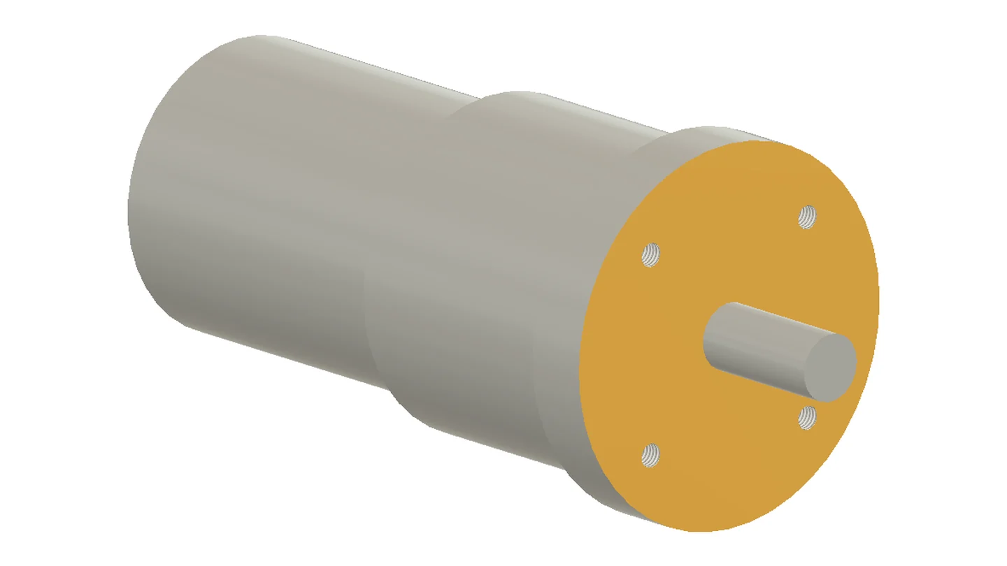
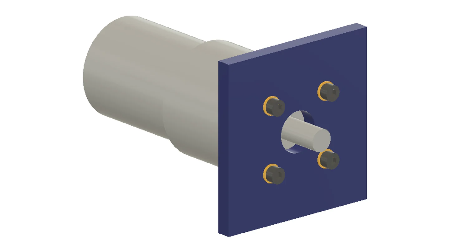
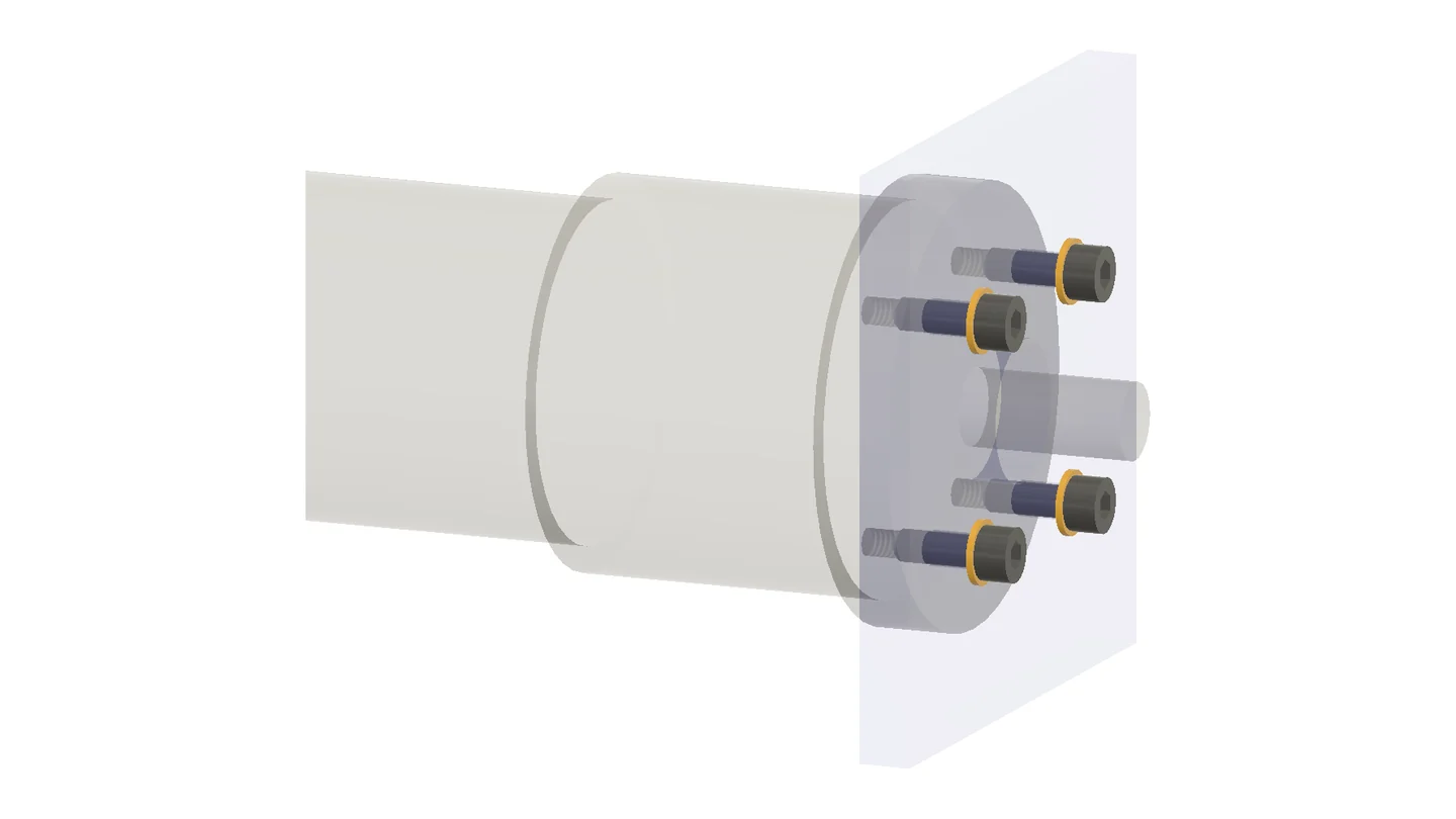
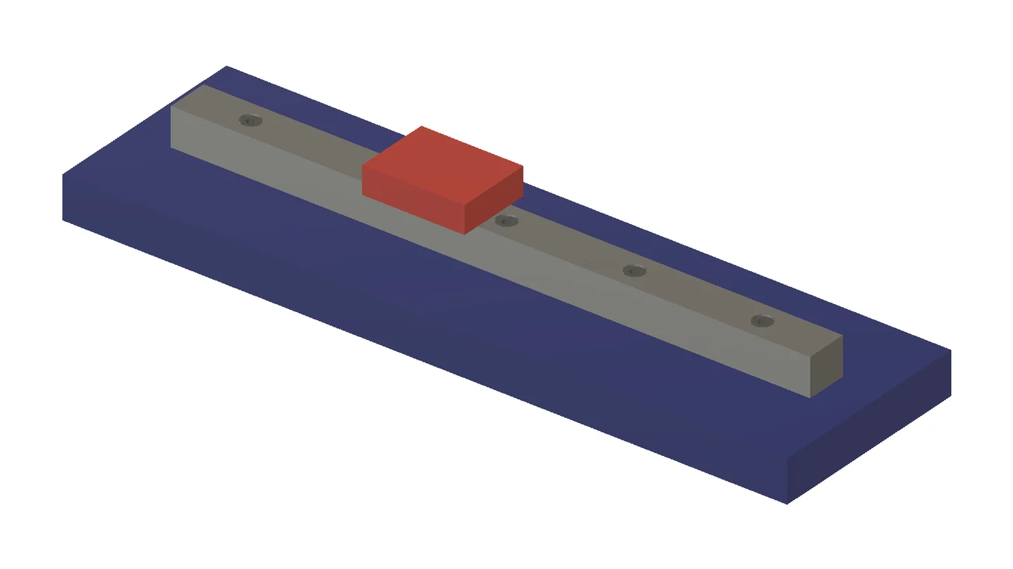
A part with threads takes the screws from your side: your parts get clearance holes, and the screws end in its threads, no deeper than the threads go. A part with clearance holes, like this linear rail, takes the screw heads: your plate is tapped or gets nuts underneath.
Fastener Stack
With Add fasteners ticked, the joint gets its screws, washers and nuts. Hole Series & Fasteners measures the parts on each hole axis and picks the next preferred screw length for the thread engagement you ask for. A screw that would be too short or would bottom out is reported before anything changes.
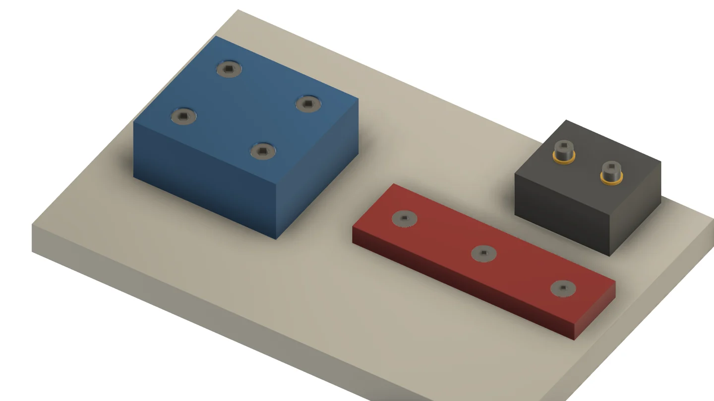
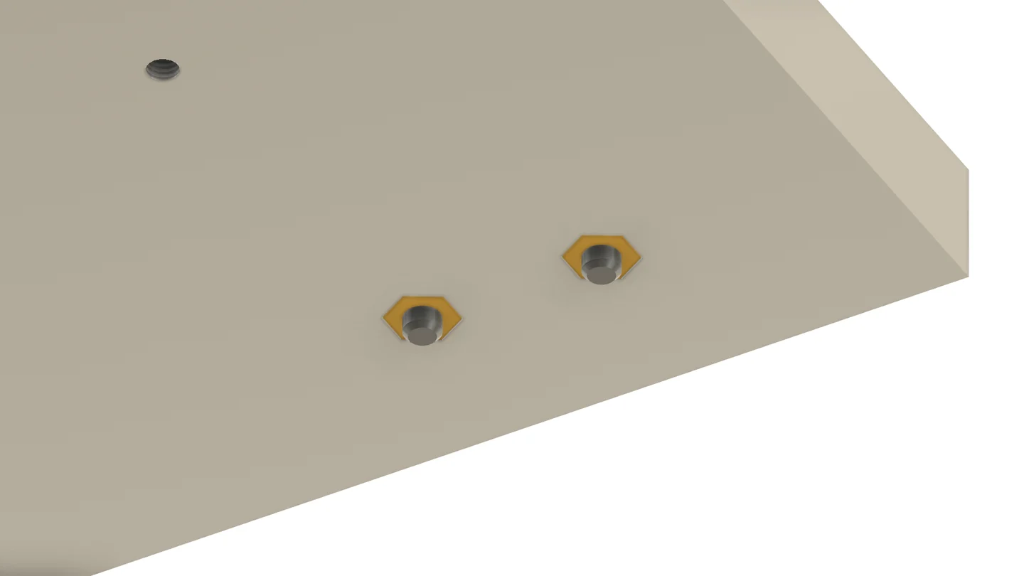
Four joints on one plate, each a Hole Series with its Fastener Stack: M10 hex flange bolts with flange nuts, M8 socket screws with nylon-insert lock nuts, M6 dowel pins in reamed H7 holes, and 1/4-20 flat head screws in 82° countersinks with lock nuts. A flange head or a flange nut needs no washer; a dowel pin gets the longest standard length that fits the joint.
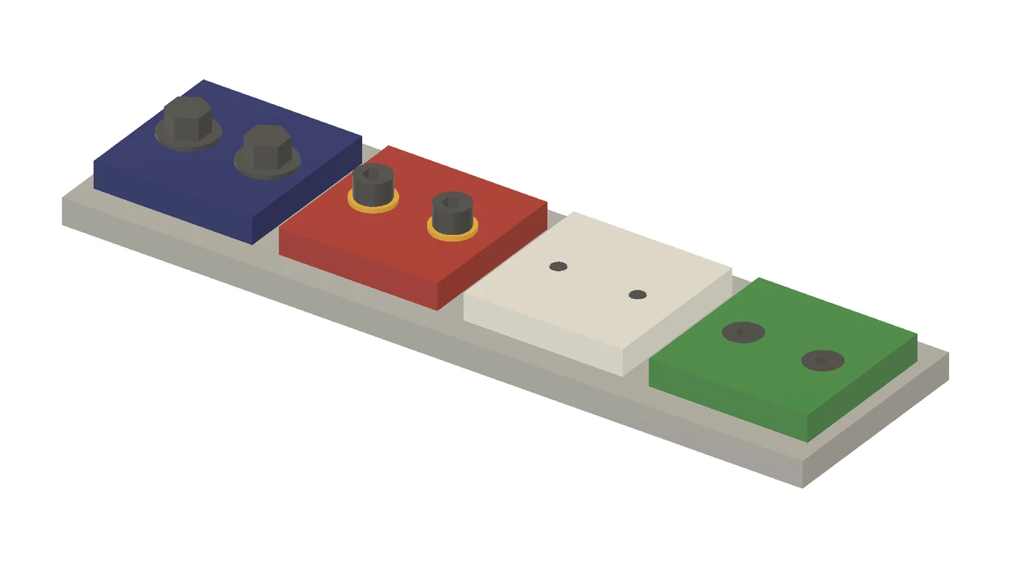
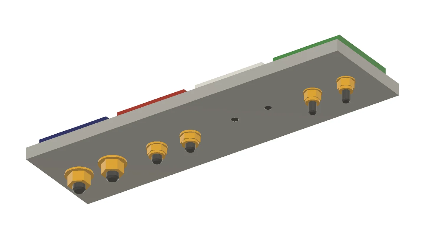
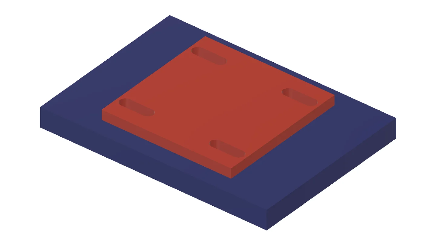
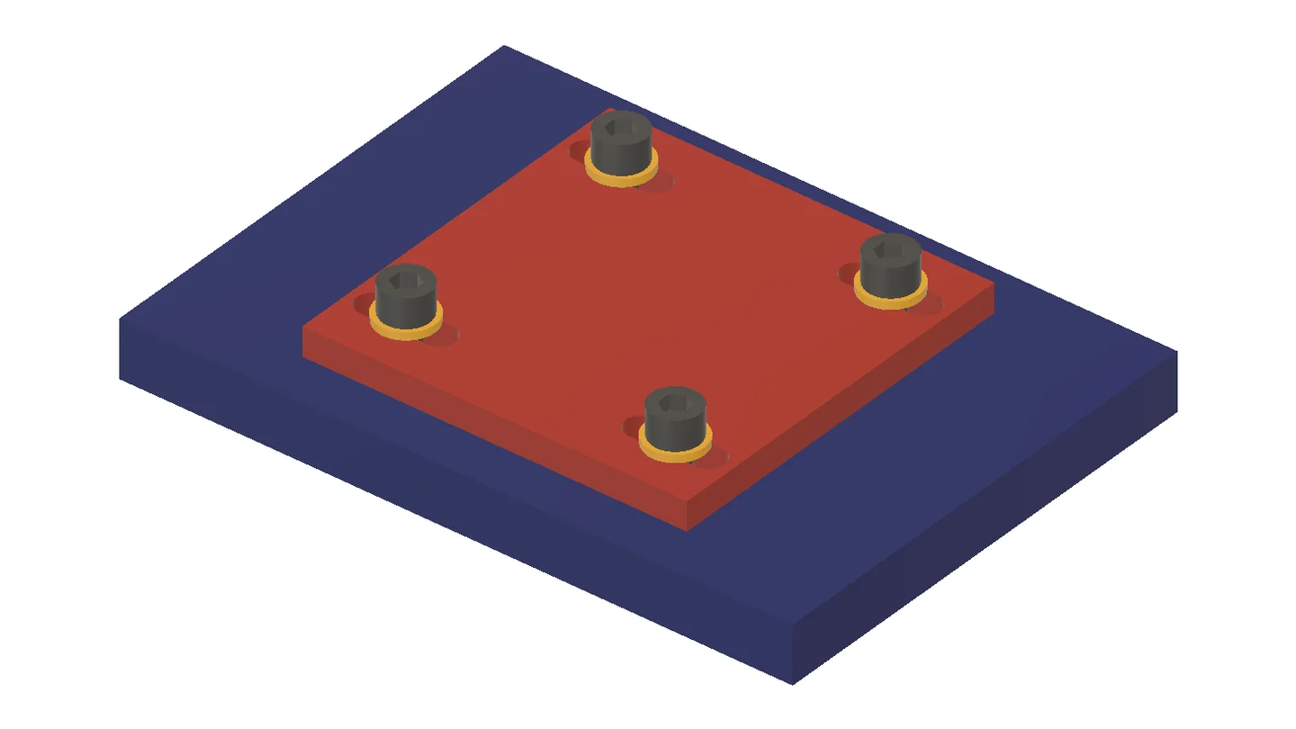
Set Slot travel and the round holes become slots as wide as the hole. Choose the part under the head, the last part or all of them; the others keep round holes. Here a motor plate gets 14 mm of travel, for example to tension a belt, and the frame under it is tapped M6. With Add fasteners, a washer covers each slot.
Socket, hex, button, countersunk and hex flange heads. Hex, nylon-insert lock and flange nuts. ISO 8734 dowel pins in reamed H7 holes.
Metric sizes with fine pitches from M8x1 to M24x2, and fourteen UNC/UNF sizes from #6 to 1/2 inch with socket, button, 82° flat and hex heads (hex from #10), hex and nylon-insert lock nuts and flat washers. Tapped holes use the exact Fusion thread.
Hardware linked to a Hole Series follows its size, head seat and far side. A nut pocket gets a captive nut. Turn a Follow option off to keep your own choice.
Screws are reference bodies without helical threads, so large assemblies stay responsive. Size, length and standard are stored for the BOM. Check purchased parts against your supplier.
Export Hardware BOM
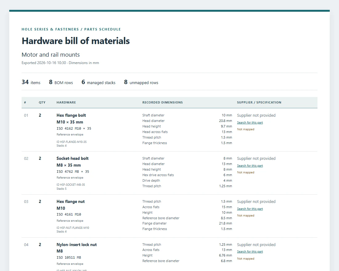
One export collects every screw, washer, nut and pin Hole Series & Fasteners placed. Matching items group by size, length and dimensions; repeated components multiply their quantities. Each row names the part the way suppliers list it, such as ISO 4762 M8 × 35, with a link that searches for it.
The sample is a larger inspection fixture: 84 items in seven rows. Grades, prices and suppliers are not filled in for you.
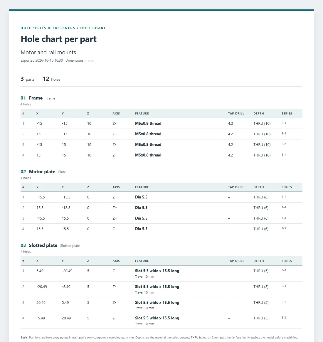
The same command writes a hole chart. For every part a Hole Series drilled, it lists each hole at its entry point in that part's own coordinates, with the axis, diameter or thread, tap drill, slot, counterbore or countersink and depth, as CSV or a printable page.
Export your saved joints (hole size, treatments, hardware) and import them on another computer, so the whole team starts from the same connections. Imports are checked before they replace anything.
Export the fastener dimensions you use and the supplier part numbers you mapped, and import them elsewhere. Existing hardware changes only when you rebuild it.
Where the time goes
The drive mount in jobs 1 to 3 has 4 part files and 3 bolted joints: 20 holes and 20 pieces of hardware. This is what it takes in Fusion by hand, and with Hole Series & Fasteners.
Each joint on this page took about a minute and a half, most of it Fusion saving the part files to the cloud. You confirm and wait; there is nothing to open, sketch or measure.
Switching CAD
Native Autodesk Fusion can cut a Hole through local bodies inside one file, or Edit in Place one external component at a time. Hole Series & Fasteners brings multi-part hole series, automatic screw-length selection and assembly cuts across linked Fusion files.
| In SolidWorks or Inventor | In Hole Series & Fasteners for Fusion 360 |
|---|---|
| Hole Series (head recess, mid clearance, threaded or clearance end) | Hole Series: counterbore, countersink or simple head; clearance middle; tapped, clearance, hex nut pocket or PEM S-M4-1ZI mounting hole on the far side — across local or linked part files |
| Slotted holes for adjustment | Slot travel in the first, last or every part of the series, with a washer over each slot (local components) |
| Smart Fasteners / Bolted Connection Generator | Fastener Stack: metric M2–M24 with fine pitches from M8x1 to M24x2 & 14 UNC/UNF sizes; socket, hex, button, countersunk and flange heads; hex, nylon-insert and flange nuts; dowel pins; all sized to the measured grip |
| Assembly Cut propagating to part files | Assembly Cut: Cut or Intersect across local or linked part files with a saved cutter that rebuilds on Edit or Update All |
| Favorite fastener templates & BOM rollup | 12 bundled + custom JSON connection recipes, Batch Change for local sizes, and Export Hardware BOM (CSV + printable A4 HTML) with order designations, search links and supplier SKU mapping |
Linked files and subassemblies
A target part can be linked straight into your assembly, or sit inside a linked subassembly, up to 5 link levels down. Select it in the top assembly as usual. Before anything changes, the confirmation lists each subassembly with the files under it.
The files are saved bottom-up: first the part with the new holes, then each subassembly with its link moved to that new version, last your assembly. A part used several times shares one definition, so the holes appear in every copy; Hole Series & Fasteners only does that when you tick All instances.
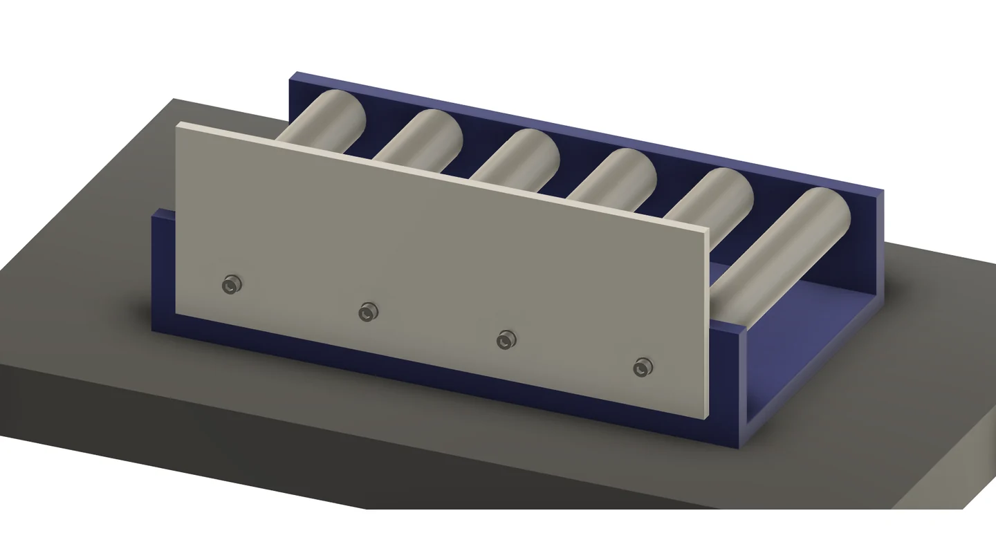
Example: a packaging line with an infeed module linked in
Your assembly is saved last, with every link on the new versions.
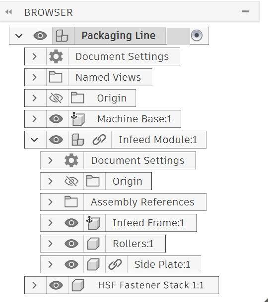
One command, every file
Each part of the drive mount is its own Fusion file, linked into the assembly. Opened on their own after the three joints, the files show their new holes: normal Fusion hole features at the right place in each file, saved as a new version.
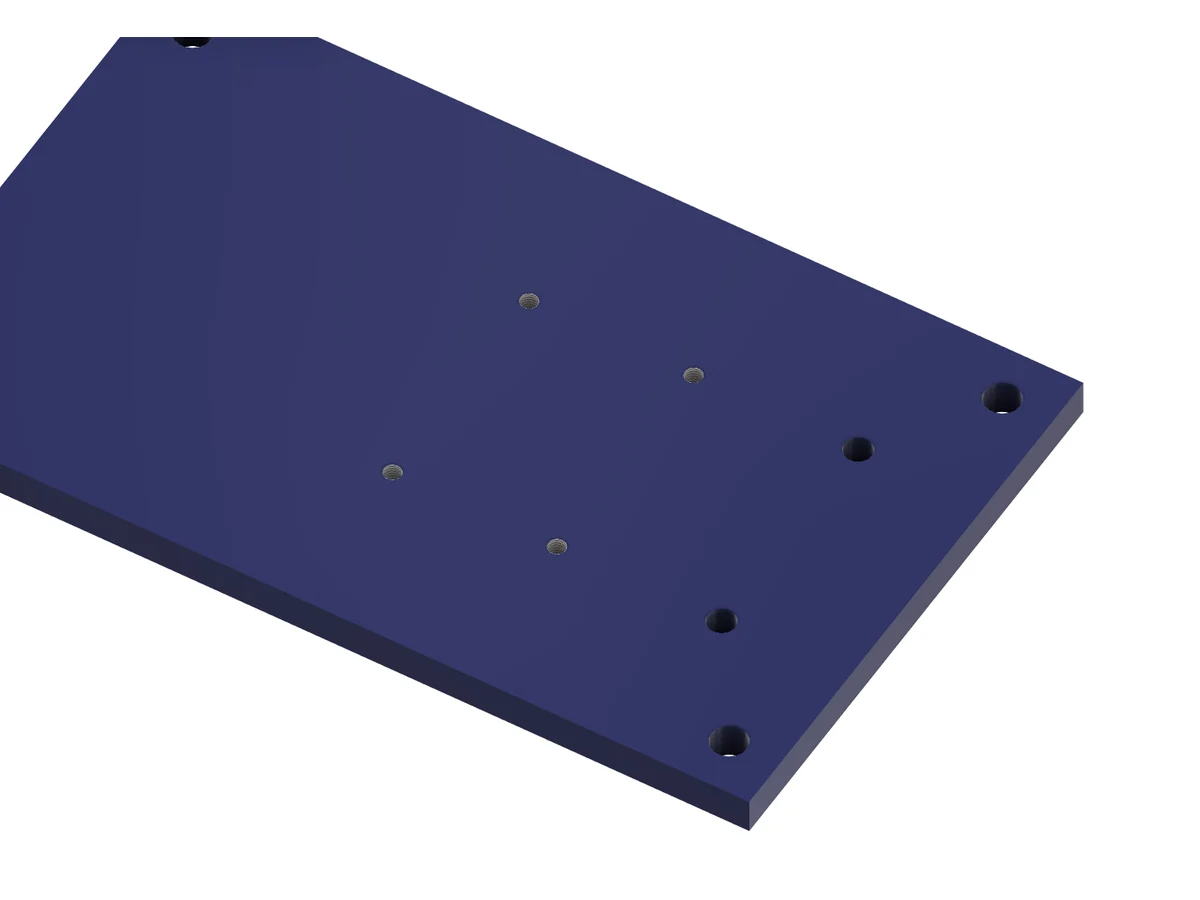
Base Plate v3
4 × M8 tapped holes for the bracket and 2 × Ø11 clearance holes for the bearing block, from two different joints.
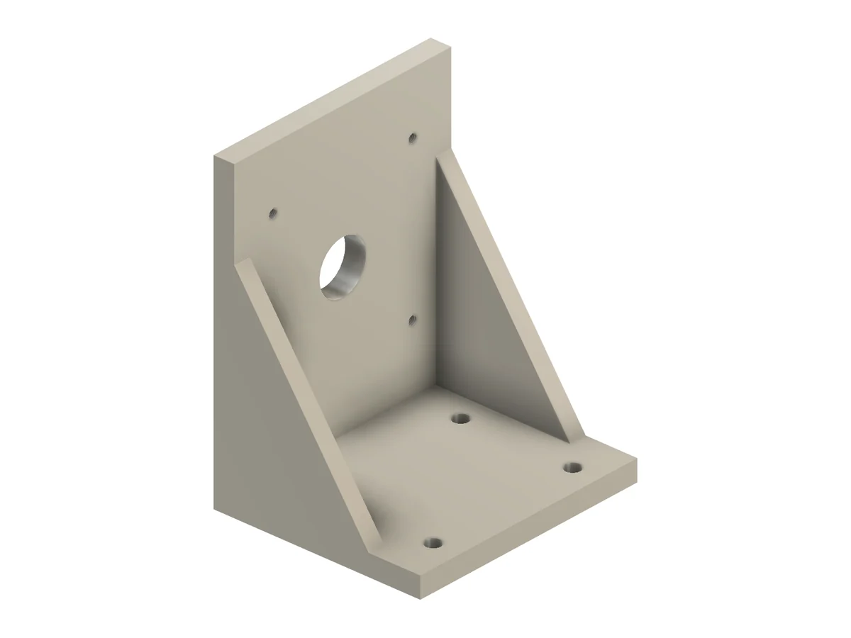
Motor Bracket v3
4 × Ø9 clearance holes in the foot and 4 × M6 tapped holes in the upright for the motor.
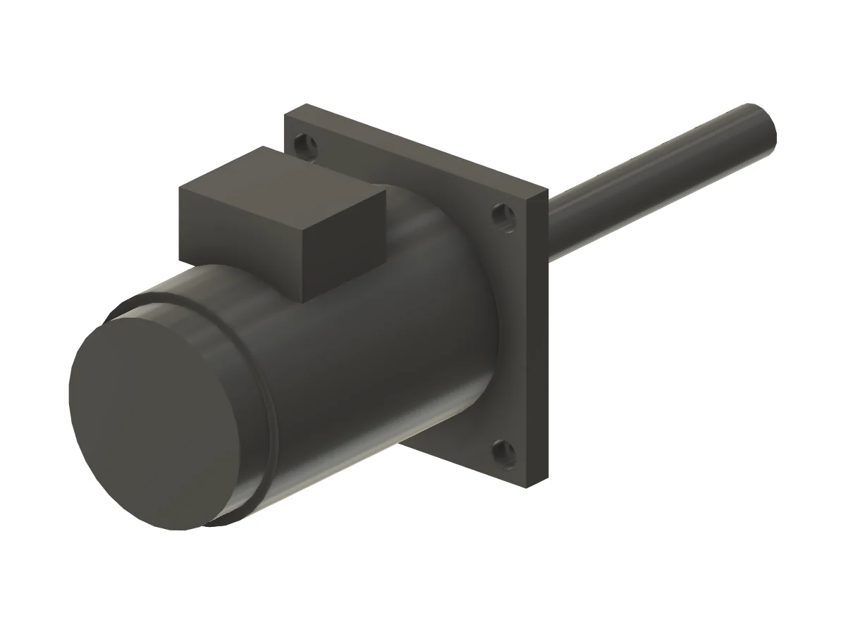
Gear Motor v2
4 × Ø6.6 holes with an Ø11 counterbore in the flange, so the screw heads sit below the face.
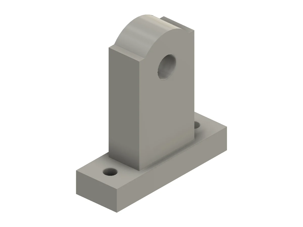
Bearing Block v2
2 × Ø11 clearance holes for the M10 bolts that go through the base plate.
The base plate and the bracket each belong to two joints, so each got two new versions. The holes on each side of a joint differ: clearance in one part, tapped in the next, a counterbore where the head sits.
How it works
Run Hole Series in your Hybrid assembly. Select sketch points, vertices, circular edges or the face of a part that already has holes as centres, then the parts to drill, or let it find the parts on the hole axis.
Thread size, metric, fine pitch or UNC/UNF. Head side: simple, counterbore or countersink. Far side: clearance, tapped or a nut pocket, and slots where a part must be adjustable. Tick Add fasteners for the hardware.
It checks every file first, then opens each linked part, adds the holes in its own coordinates, saves it and brings the assembly back with the links updated.
Change size, type or positions with Edit Assembly Feature, under the same rules as Create. After parts move, Update All rebuilds every joint in order: holes, cuts, then hardware. Audit checks everything before release.
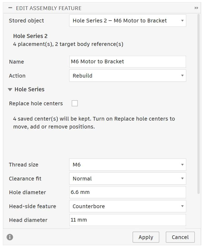
The assembly keeps each joint as one managed object: its centres, parts, sizes and hardware.
Nine commands
Hole Series, Fastener Stack and Assembly Cut sit on the ribbon; the rest are in the Hole Series panel menu.


Aligned holes through every selected part: clearance, counterbore or countersink on the head side; clearance, tapped or a nut pocket on the far side; slots and H7 dowel holes. Pick a motor or rail face to use its holes.

Screws, flange bolts, dowel pins, washers and hex, lock or flange nuts in the holes, with lengths picked from the measured stack and the thread engagement you ask for.

Change a saved joint: size, treatment, hole positions or the cutter of an Assembly Cut. Linked files are updated again for you.

Rebuild every managed joint in order after parts moved or changed shape.

Twelve ready recipes and your own. Change the size of selected connections together, for example M5 to M8.

The hardware grouped and counted, each row with its order designation and a search link, as CSV or a printable A4 page. Also a hole chart per part.

One Cut or Intersect through several parts, local or linked, such as a cable passage, kept editable.

Check every managed joint before you release drawings: missing or changed geometry and references.

Help, version, license status and support.
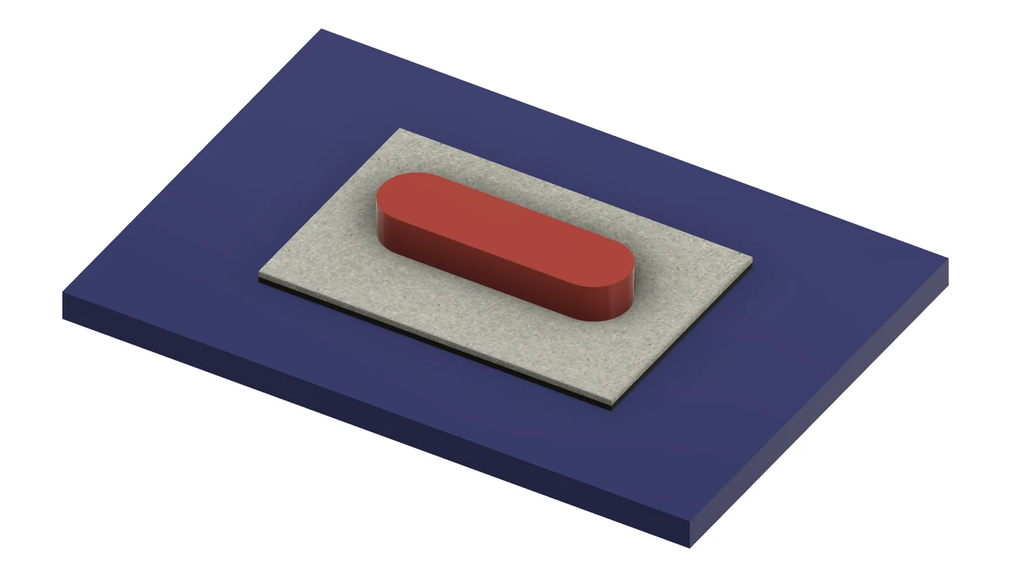
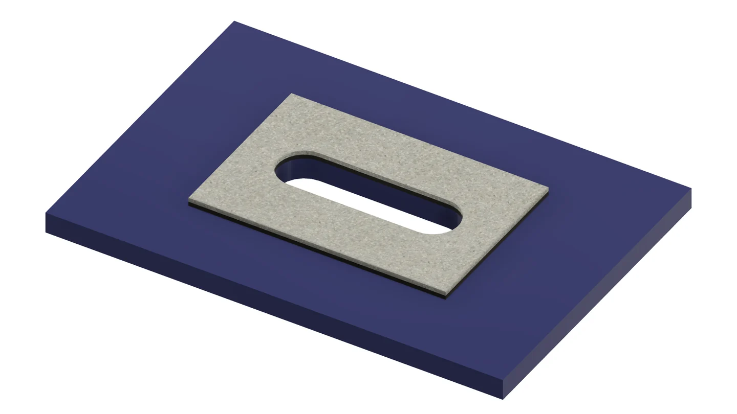
Model the cutter once, select the parts it goes through and run Assembly Cut. Each part gets the cut in its own file, linked parts included, and the cutter is kept so the cut can be edited, updated or deleted later. Here, one cable passage goes through a machine base, a gasket and a gland plate.
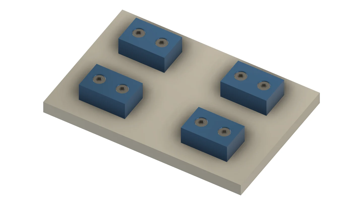
Start a Hole Series from one of twelve recipes (tapped fixtures, through bolts, a captive nut, a flush panel, UNC/UNF examples, a PEM mounting hole) or from your own saved joint. To change a size across a design, filter the connections by their current size, select them and preview the change before OK. Here, on a fixture built from components of the assembly itself, one Batch Change turns four M5 joints into M8: holes, counterbores, threads and screws.
Read the connection library guide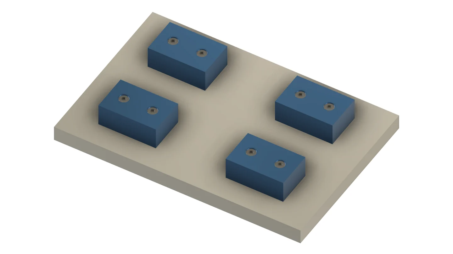
Hole Series & Fasteners v1.0.1 · Windows
US$49/year per useror US$8/month
The user guide covers each command, the linked-file rules, the hardware sources and what to do if a job stops.
Before you start
Insert Fastener places library fasteners on geometry that is already there, such as existing holes. Hole Series & Fasteners makes the holes: the matching hole in every part of the joint, with the right type on each side. It adds the hardware with a length that fits, and when you edit the joint the holes and the hardware change together, also across separate part files. It also gives you a hardware list with order designations and a hole chart per part.
In native Fusion, bolting external linked components (xrefs) together means opening each file, or using Edit in Place + Project or Insert Derive, cutting clearance and tapped holes separately, and placing Insert Fastener or McMaster-Carr parts by hand. Hole Series & Fasteners brings a SolidWorks Hole Series / Inventor Bolted Connection workflow to Fusion: define the joint once in the assembly, and it drills the matching clearance, counterbore, countersink, tapped, nut-pocket, slotted or H7 dowel holes into every local or linked part file, places sized hardware, and updates every file when you edit the joint.
No. The parts can be components of one design; then there are no files to save. Separate linked part files, also inside linked subassemblies up to 5 levels deep, are where it saves the most time: each file is drilled, saved and its link updated for you.
Email support@vanthanbk.com for the trial build; we reply with the current build and the install steps. The 3-day trial starts the first time you run a modeling command while signed in and online. To keep it: US$49/year or US$8/month per user. Windows only; macOS is not in this release.
It removes the per-file work: on the drive mount on this page, 20 holes in 4 files and 20 pieces of hardware took 3 commands of about a minute and a half each.
Yes. Pick the motor's flange face: its holes become the centres, your bracket gets clearance holes and the screws end in the motor's threads.
Yes. Each part file gets ordinary Fusion hole features in its own timeline, at the right place in its own coordinates. Fusion drawings, CAM and other tools see normal holes. Where a hole enters a round tube or another curved face, the part gets a plain drilled cut instead.
Run Update All. Hole Series & Fasteners measures every joint again and rebuilds them in order. When the hole centres come from the part that moved (an edge, a vertex or a sketch point on it), the holes in every file and the hardware follow it to the new place, and the changed files are saved again. If a linked part was changed outside the assembly, use Get Latest in Fusion first.
Yes. In Edit Assembly Feature, turn on Replace hole centers and select the complete set you want; the dialog shows the saved and new positions before you confirm.
Metric and UNC/UNF screws, washers and nuts, and ISO 8734 dowel pins in reamed H7 holes, all as dimensioned reference models, not certified supplier parts.
Yes. Each row names the part the way suppliers list it, for example ISO 4762 M8 × 35 or ISO 10511 M8, with a link that searches the web for it. It counts the hardware Hole Series & Fasteners placed, repeated components included. Your company catalogue can add a grade per kind of hardware, such as 12.9 for socket screws, point the links at your supplier's search and map your own supplier part numbers. Grades, prices and supplier numbers are never made up for you.
Yes, as its own export: Export Hardware BOM also writes a hole chart per part, with each hole's position in that part's own coordinates, its axis, size or thread, tap drill and depth, as CSV or a printable page. It is not a hole table on a Fusion drawing, and holes made by other Fusion features are not listed.
Hole Series & Fasteners checks every file before it changes the first one, so most problems stop it with no file changed. If a later file fails, the versions already saved stay in the cloud: the message lists which files were saved and which were not, and Update All can release the job after you have checked them.
Supported scope
Check these against your file structure before you start.
Windows only for now. Create, Edit and Update run in a Hybrid design with Capture Design History; document types are not converted for you.
Parts linked directly or inside linked subassemblies, up to 5 levels. Configured, derived, read-only and out-of-date parts are refused before any file changes, and so is a nested part reached through two subassemblies.
A linked joint keeps its set of part files; to add or remove one, delete and create the joint again. Recipes, Batch Change and slots work on local components only.
Files are saved one after another. Versions already saved stay if a later file fails; there is no rollback of several files together.
A mounting face reads round holes only. A size read from a hole diameter is a best match: check it before OK.
Screws are dimensioned reference models without threads. Sizes without sourced data, such as fine-pitch button heads or dowel pins above 20 mm, are refused instead of guessed.
Planned improvements
Not in the current release, and without release dates.
Manual length, thread engagement, washers, nuts and the Follow options for the hardware of a linked joint, in Edit Assembly Feature.
Reuse recipes and change sizes of selected joints whose parts are linked files, with the same file checks and recovery.
Joints on configured designs and derived parts, with clear rules for shared definitions and update order.
Need one of these? Tell us about your assembly so we can work on a real case first.
More for Autodesk Fusion (Fusion 360)
Frames, joints and cut lists
 Steel Frame & Weldments Pro
Tube folding, welds and frame analysis in Fusion
From tube routes to fabrication packages
 Sheet Metal & Press Brake
Bend sheets for the press brake, from the Fusion flat
 Auto Backup & Export
Local backups of your Fusion cloud designs