V-notch, fold & unfold
Make a connected run from one tube, with folds in different directions, tab/slot seams and a straight STEP export.
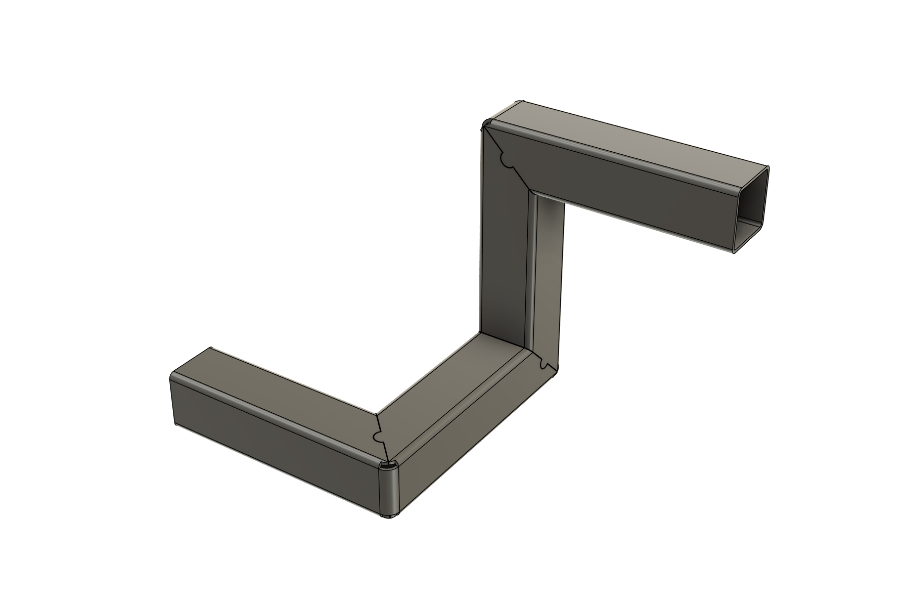
Fold several corners from one tube. Model the welds. Check the frame. Turn your Fusion design into notched tube blanks, weld schedules, cost estimates and cutting files for the shop.
US$89/year or US$12/month, per user · free 3-day trial on your own model.
With an active Standard license, try V-Notch & Fold, weld modelling and Frame Check on your own frame for 7 days. See how Pro helps with your work before deciding to buy.
Windows and macOS builds
Download ProMake a connected run from one tube, with folds in different directions, tab/slot seams and a straight STEP export.
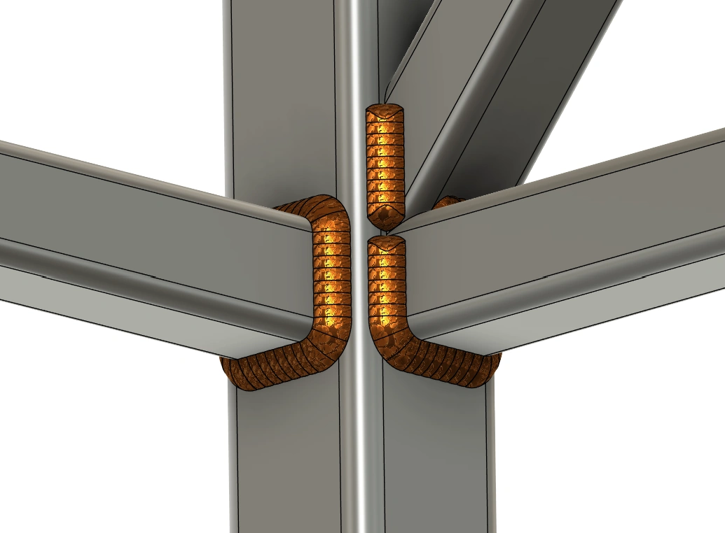
Build the beads, review the seams, and produce a weld schedule with quantities and cost estimates.
Apply loads and supports, compare load cases and design versions, and save the beam analysis with its assumptions.
01 / V-Notch & Fold
Design square and rectangular tube frames in Fusion, then turn a connected run of members into one notched, folded part. Keep the outside wall as a hinge, add optional tabs and slots at the weld seams, and export the straight tube for cutting. Fewer separate pieces to position when assembling table legs, furniture frames, guards and brackets.
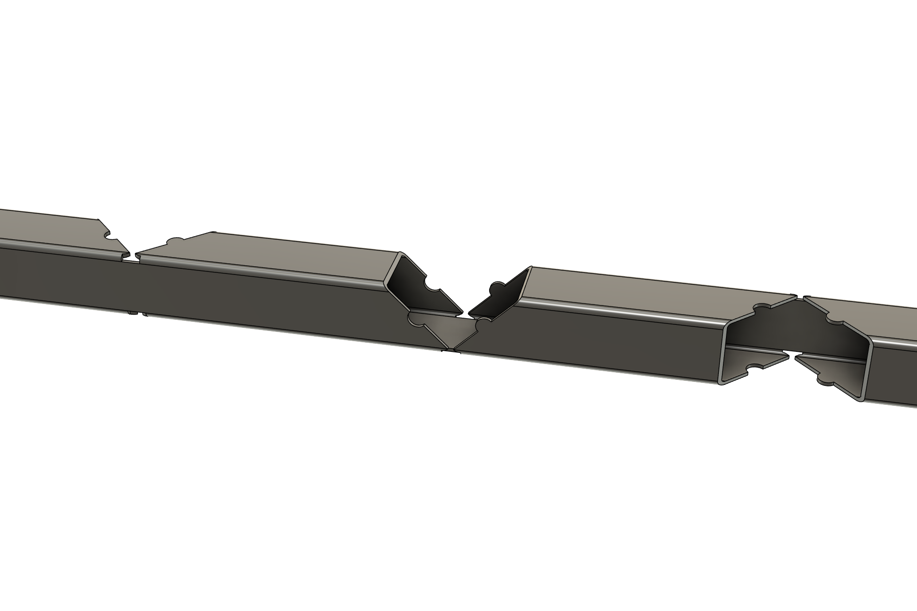
Choose outside bend radius, K-factor, weld gap, tab diameter and relief. Apply common settings, then use Corner overrides only where a bend needs something different.
Edit Fold loads the saved members, settings and corner overrides. Add members to the run or change a setting. Supported Edit Frame changes also rebuild the folded part.
Cutting List records one folded part with its developed length and notch table. PDF/CSV reports include fold data, and Stock Optimizer uses the straight blank length.
Match the K-factor to a test bend. STEP provides geometry for your shop's CAM workflow; export again after editing the frame or fold.
02 / Weld modelling & estimating
Find the seams, model the beads, review the quantities and price the work. Explore each part of the welding workflow below.
Improved fillets follow supported rounded corners and angled contacts into straight runs. Brace-to-rail side seams previously missed are included, and supported planar gusset tips with different fillet sections now connect.
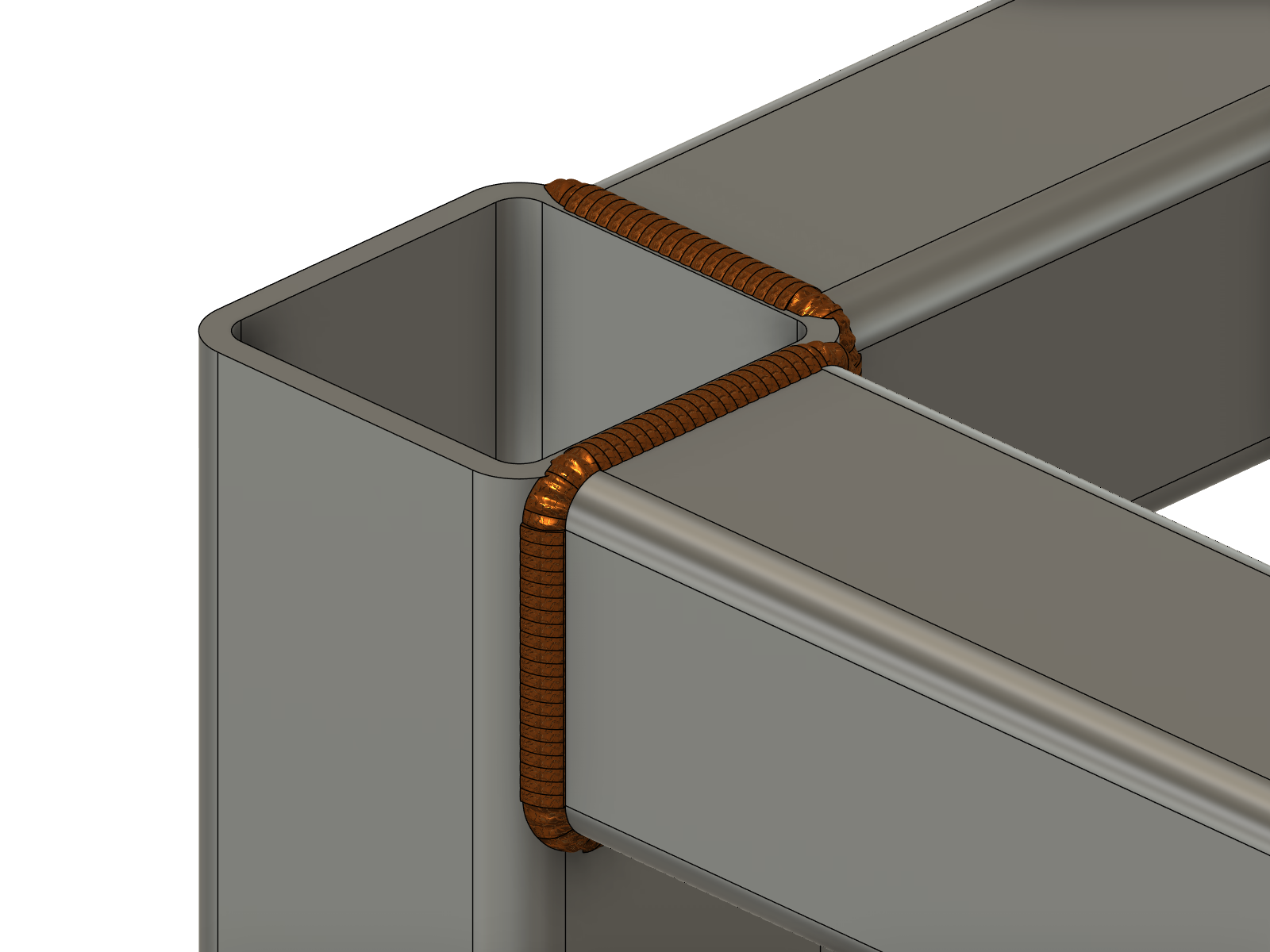
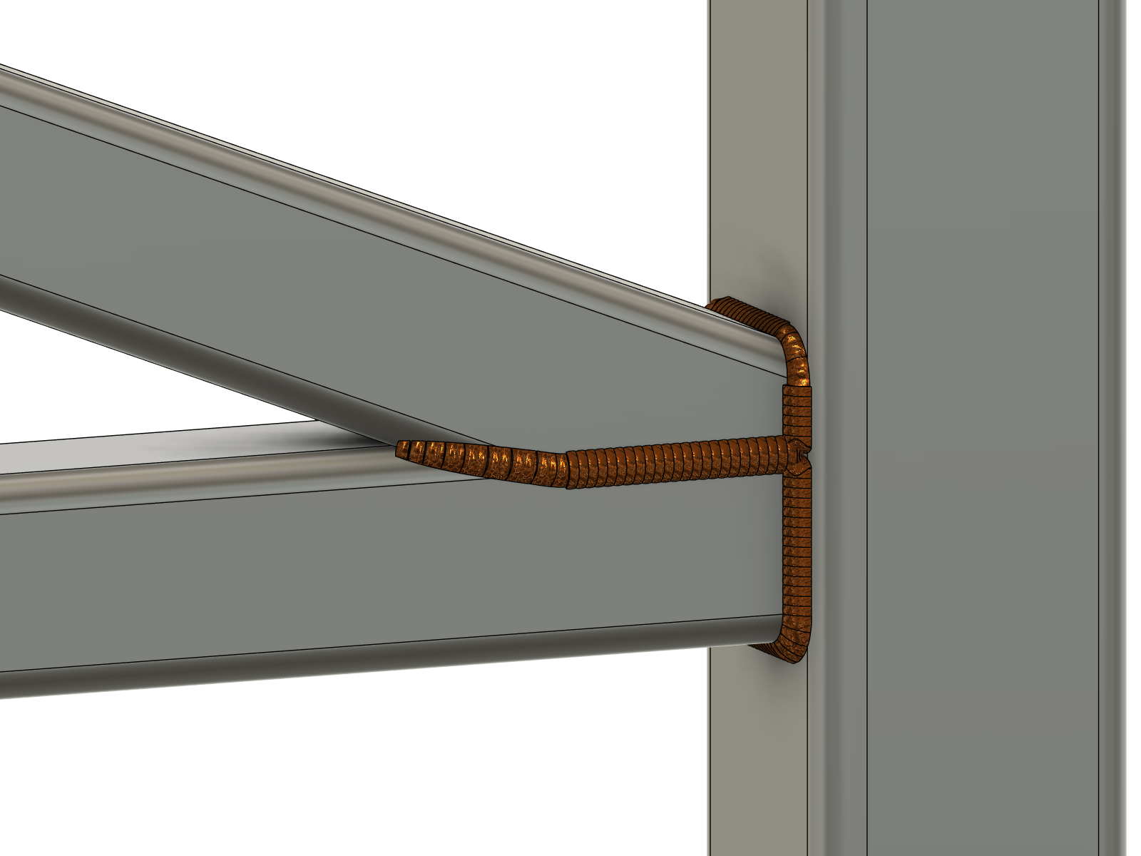
Preview seams before building. Missing support, holes or ambiguous contacts can still leave separate ends or counted-only intervals. Surface boundaries can remain between connected bead sections; curved quantities remain estimates.
Fill an existing Square, V or Bevel preparation along a straight joint or around matching round and rectangular tubes, including supported rounded box corners. Preview, create and rebuild from saved parameters.
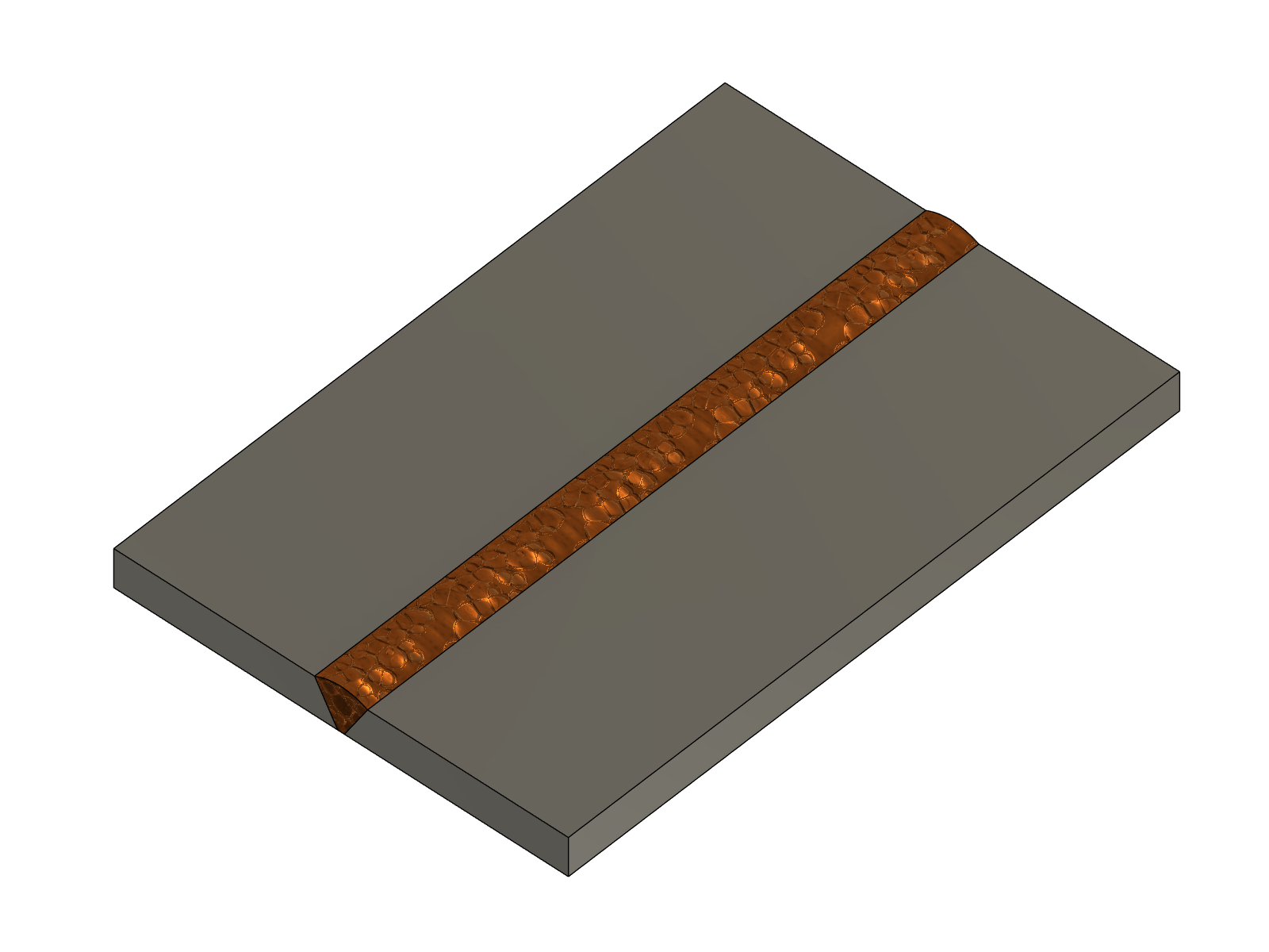
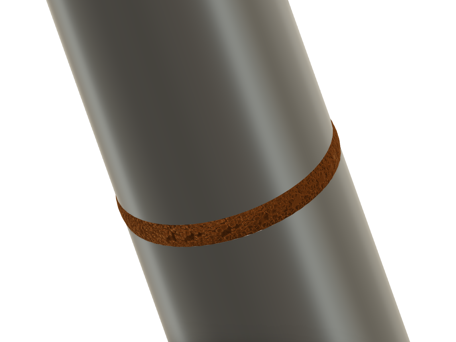
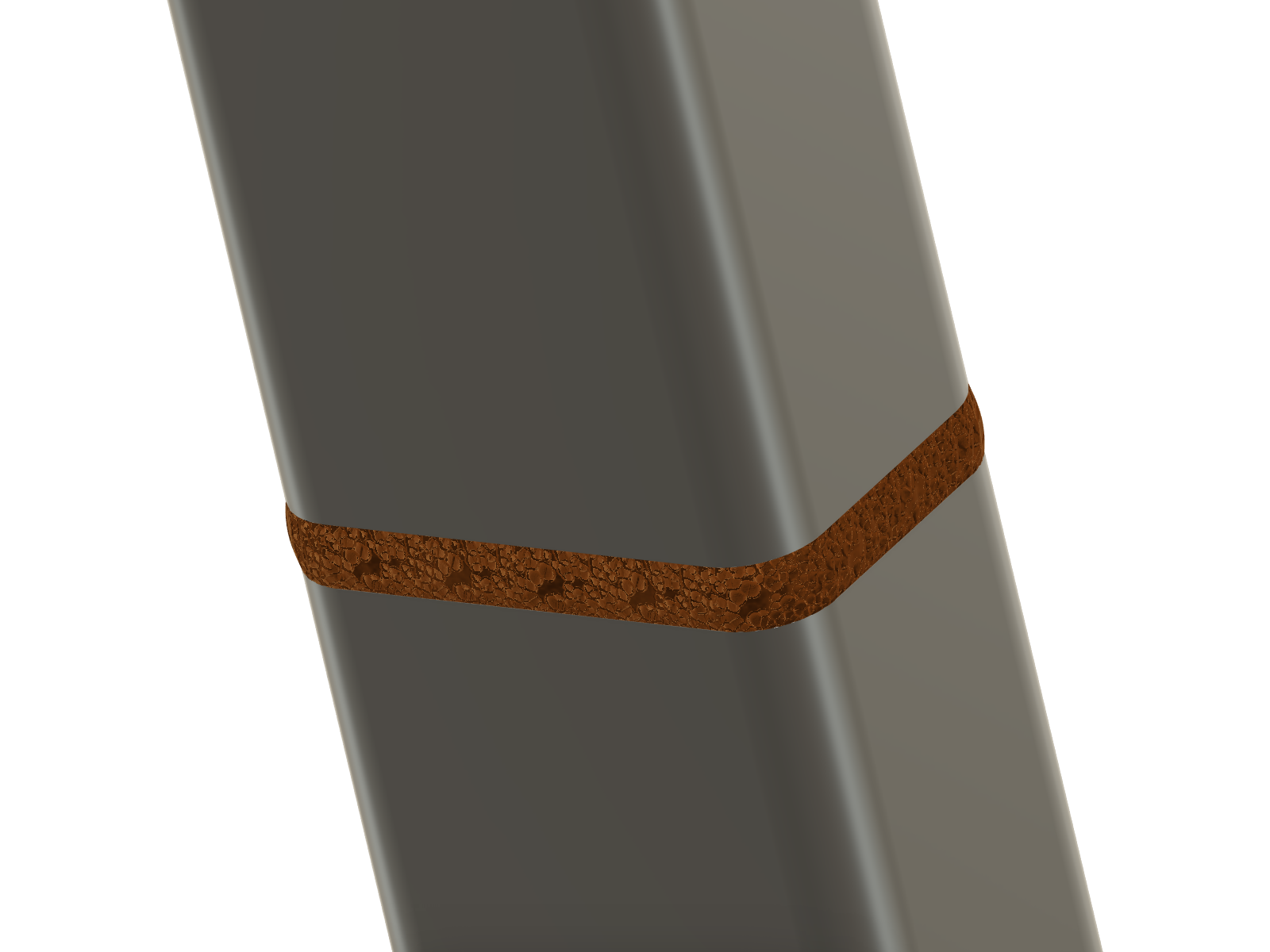
No automatic preparation or verified penetration. Oval, freeform and oblique-cut tube rims, unequal box corner radii and intermittent grooves are outside the current scope.
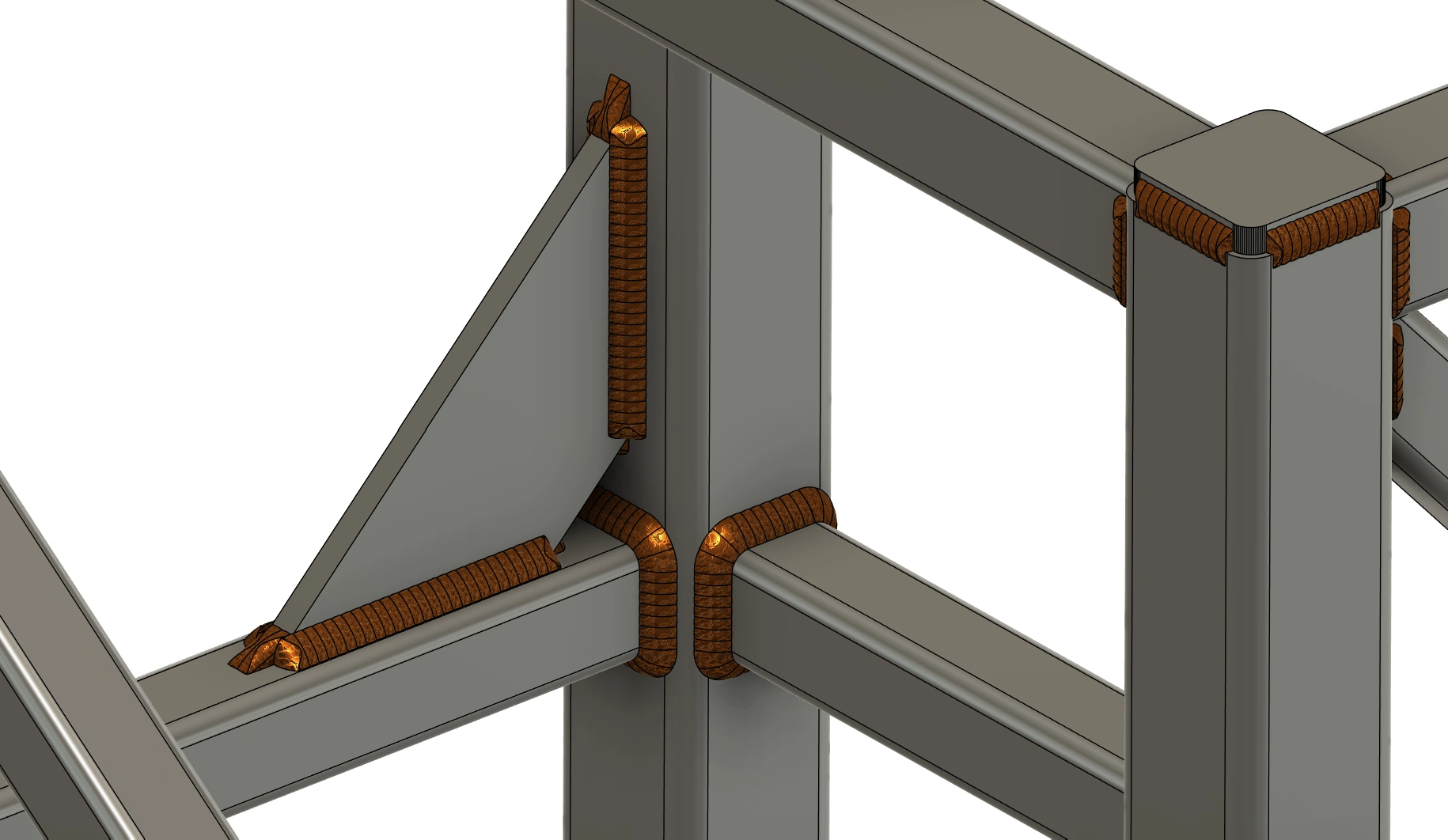
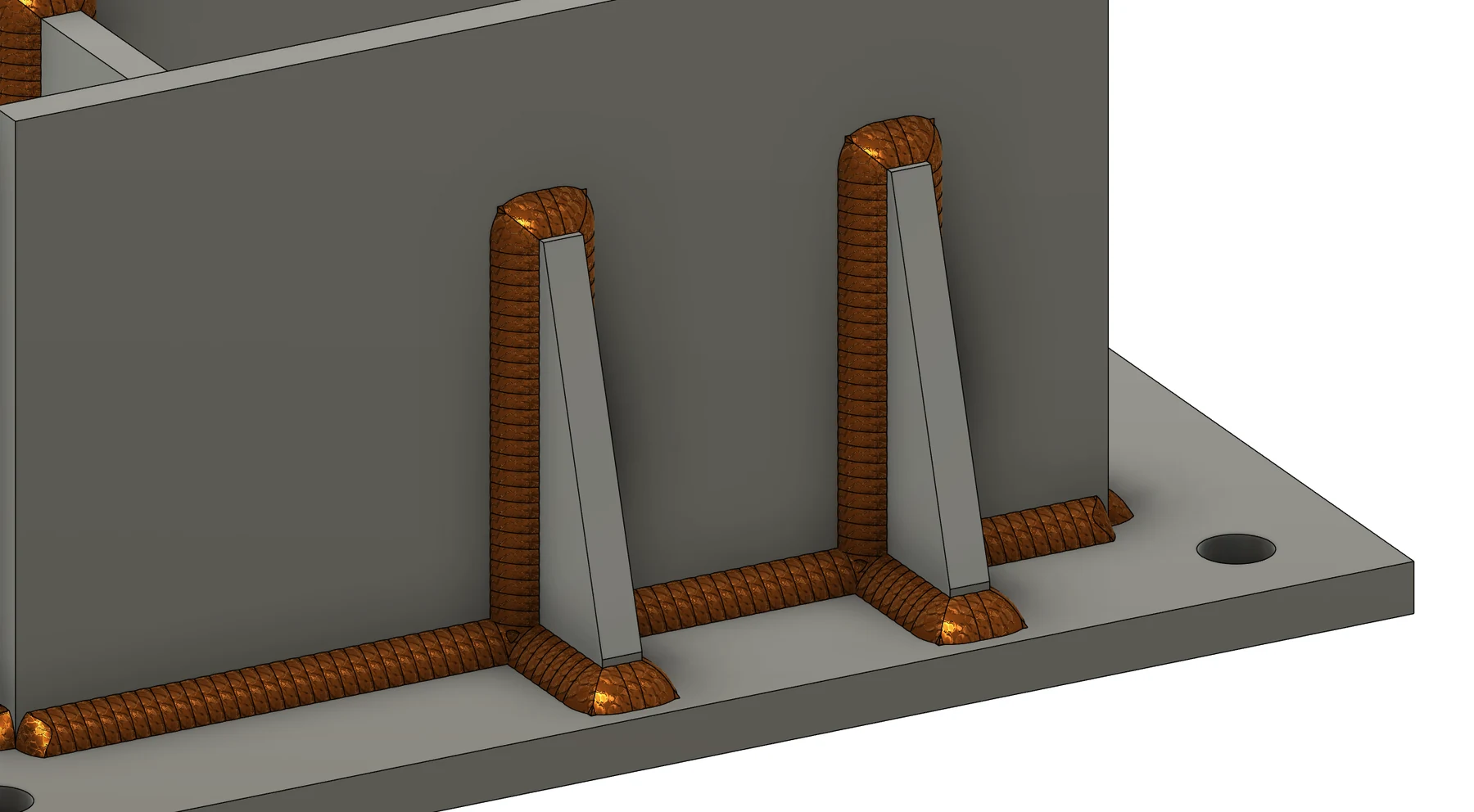
Joint IDs, fillet/cap and groove lengths, bead counts, deposited metal and fabrication notes carry into Cutting List, PDF and CSV. Optional weld tags connect overview joints to the WELD LIST; fillet symbols include leg size and intermittent length/pitch.
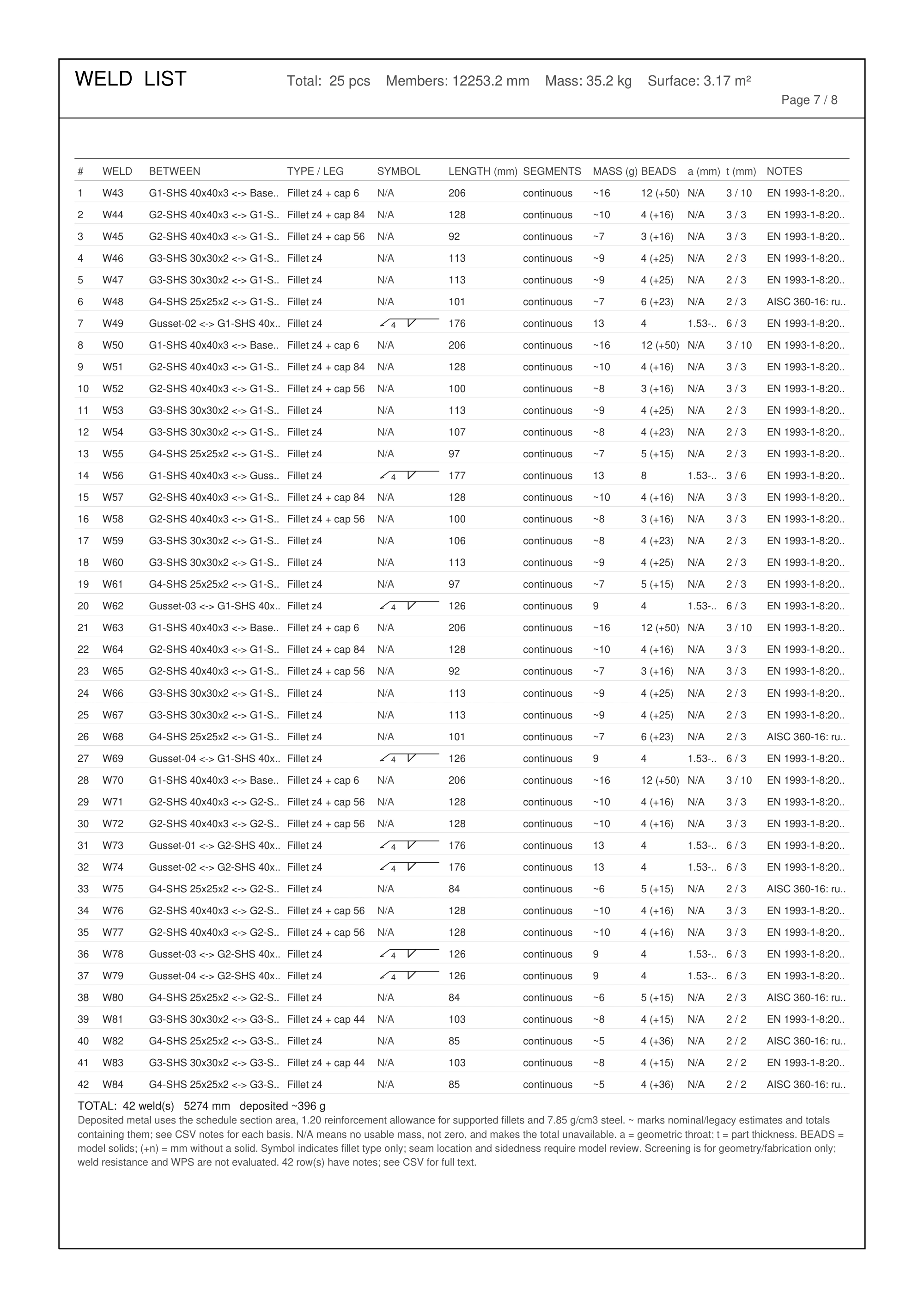
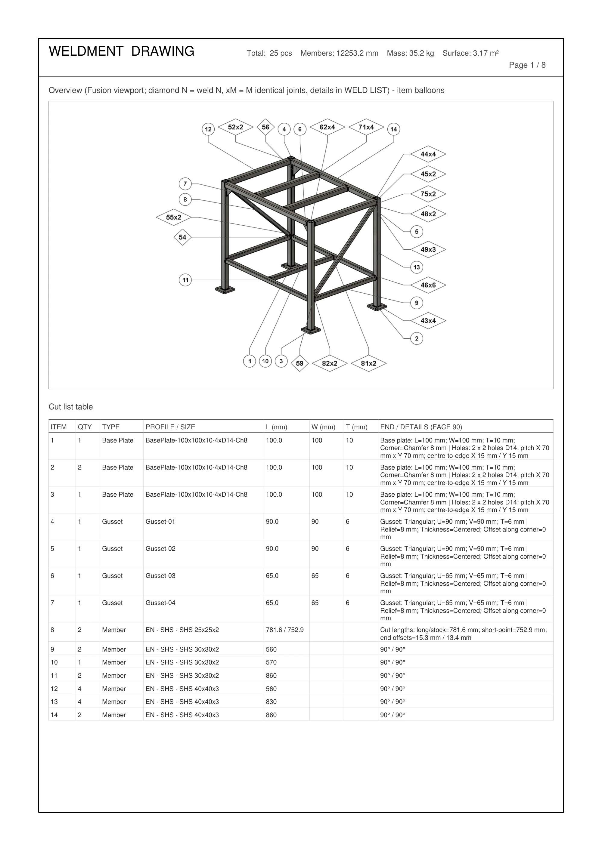
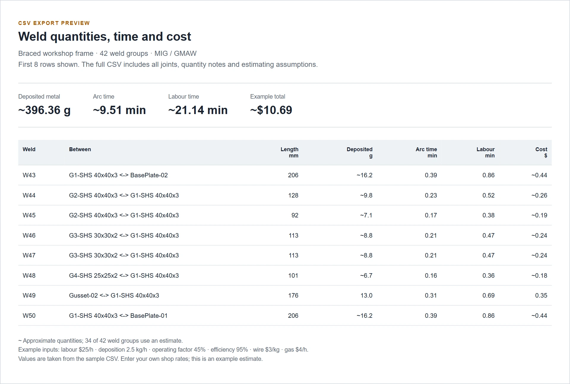
~ marks approximate quantities and N/A marks missing information. Choose whether deleted bead bodies are deducted; older rows use a labelled proportional estimate. Quantities estimate consumables, not weld strength.
03 / Frame Check
Loads, supports, member forces, stress and deflection in one Fusion workflow. Save load cases, compare and combine them in Frame Studies, and keep reports that explain the assumptions.
Results update automatically as you change loads, supports or material. Turn on Model setup to inspect the exact analytical axes, shared nodes and projected load/support positions without solving. Turn it off to return to results; its display options are hidden until needed.
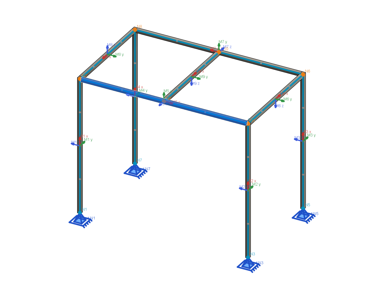
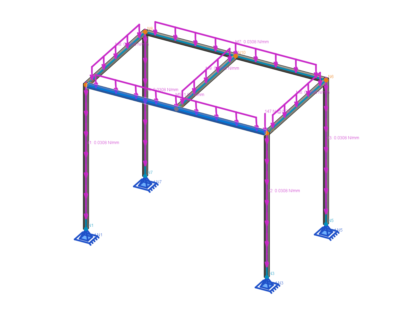
Toggle loads, supports, local axes and labels independently; a visual crossing alone does not create a connection or verify the weld.
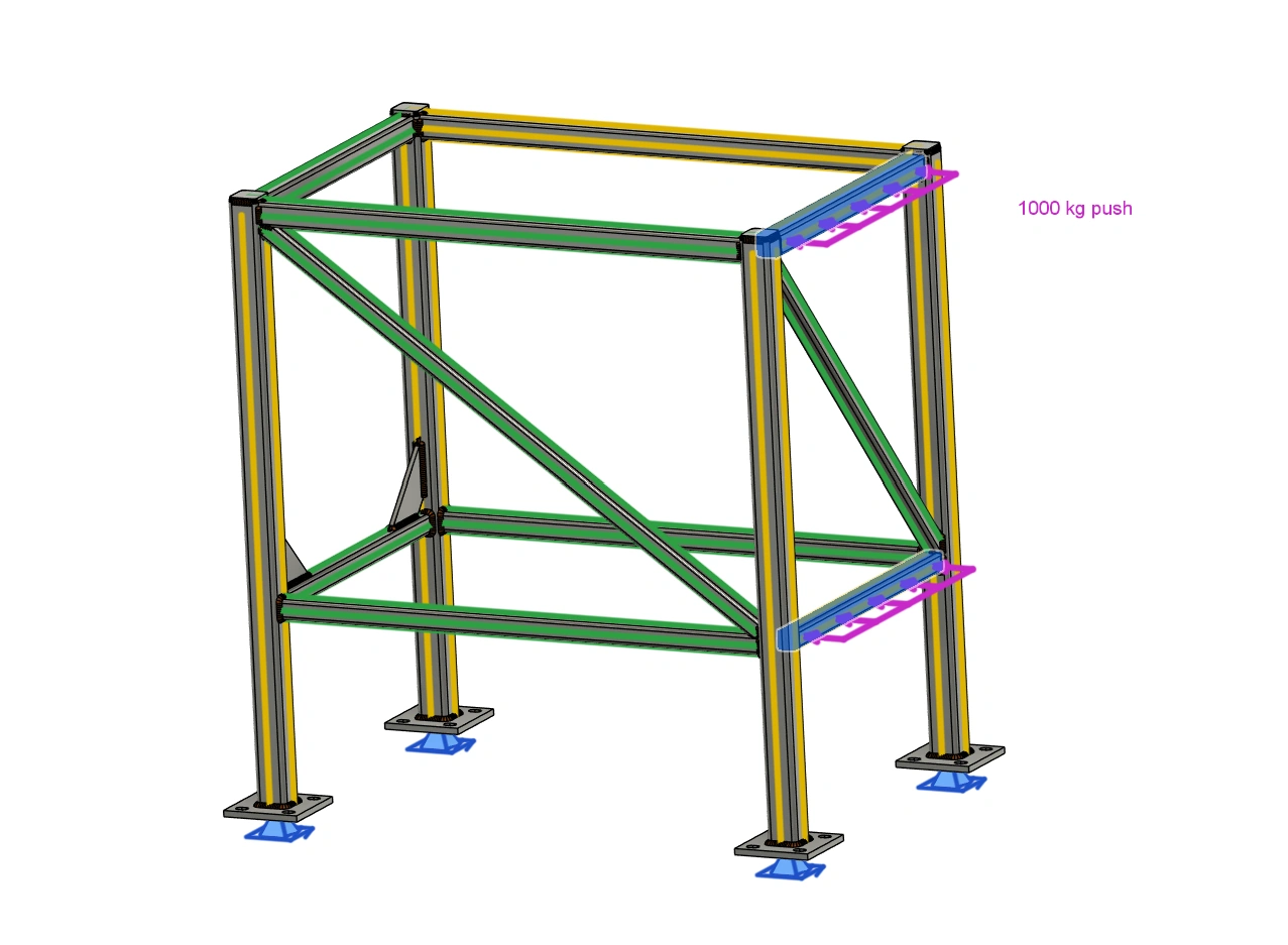
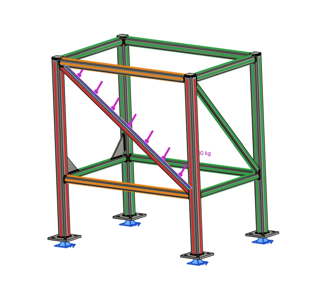
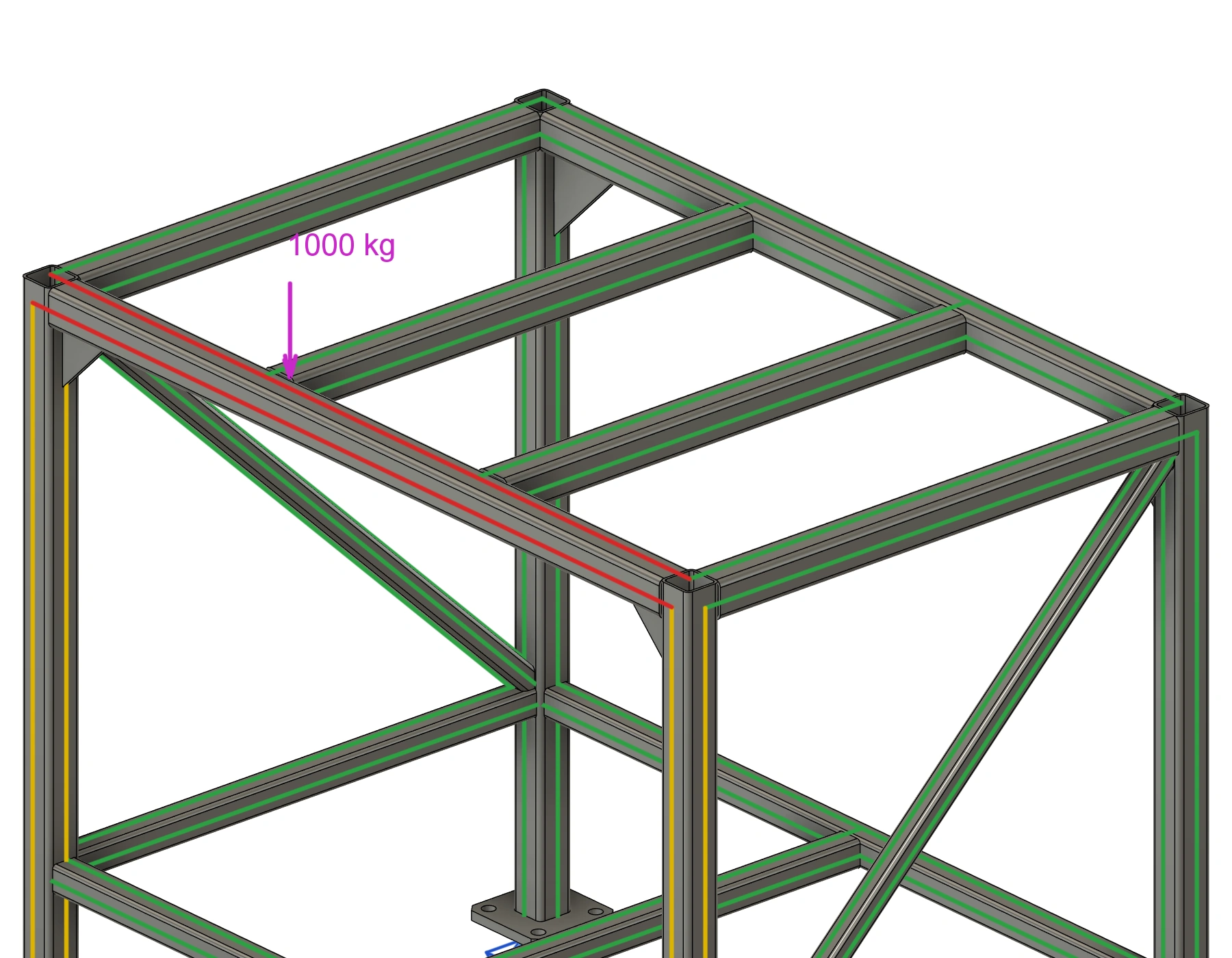
Factors are yours, not prescribed by a design code; Frame Studies uses the same beam model as Frame Check.
Frame Studies step by step →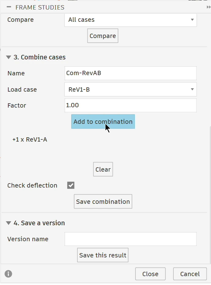
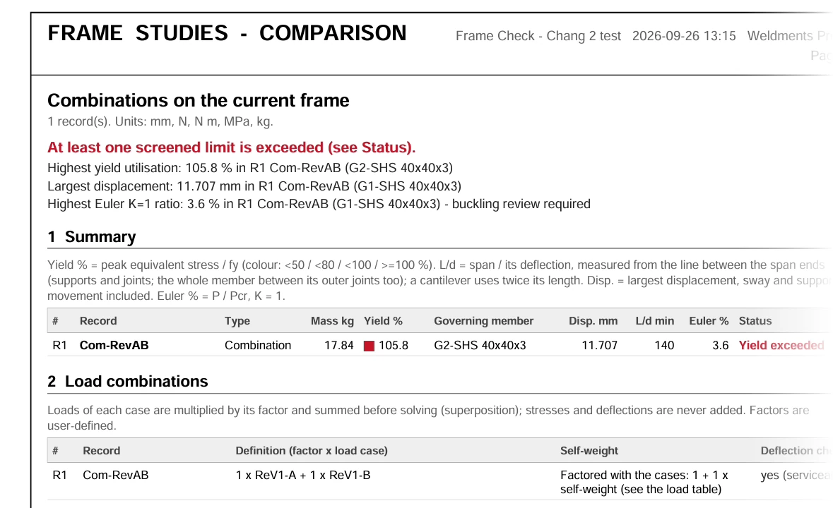
Straight Weldments members use their saved section and rotation, including RHS and I, U/C, L and T profiles. Custom rectangles, circles and concentric circular tubes are supported. Materials can use presets or your own yield strength, elastic modulus and density.
Recognises supported sharp thin-wall RHS, I, U/C, equal-wall L and centred T outlines, including rotated profiles and split sketch edges. Bending uses the actual sketch; torsion uses the stated open- or closed-section thin-wall model.
Arbitrary, T-slot and V-slot outlines still require a verified torsion model.
Member colours show stress utilisation. Review axial force, shear, bending, torsion and displacement, then export the model overview, member results and CSV with the loads, support assumptions and review notes. The deflection limit is checked per span between supports and joints; cantilevers, including arms or gates hanging from one post, use twice their length, and the largest displacement is reported separately.
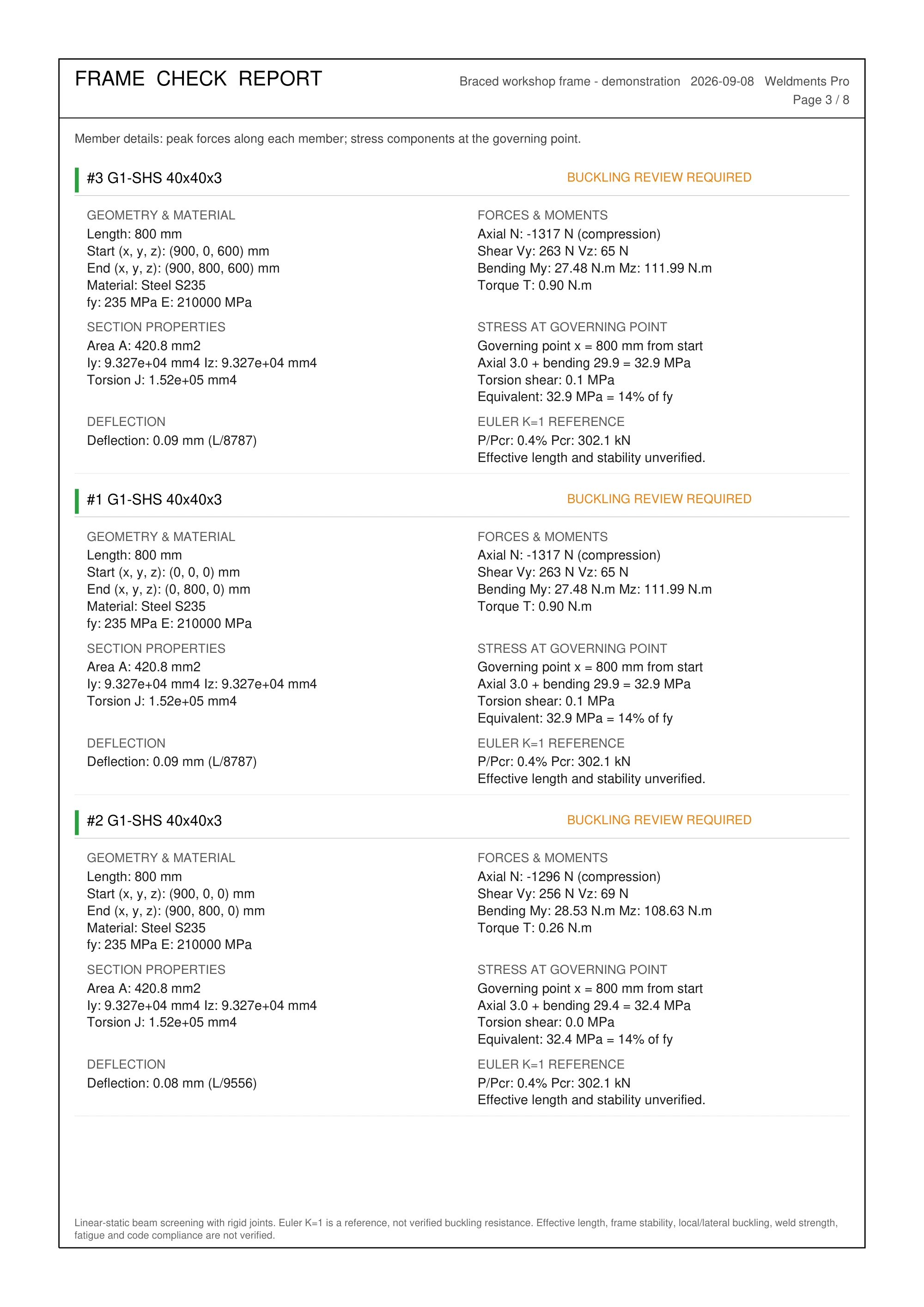
Idealised linear-static 3D beam analysis: compression requires buckling review even within stress/deflection limits.
Open the sample Frame Check PDF →See it in action
Start with V-Notch & Fold: turn frame members into a folded tube and export its notched straight blank. Then explore weld modelling, quantities and cost estimates, or check loads and compare design versions with Frame Check and Frame Studies.
Also in Pro / Fabrication tools
Locate the parts, order the stock and export the cutting files. These tools support the welding and frame workflows in the same project.
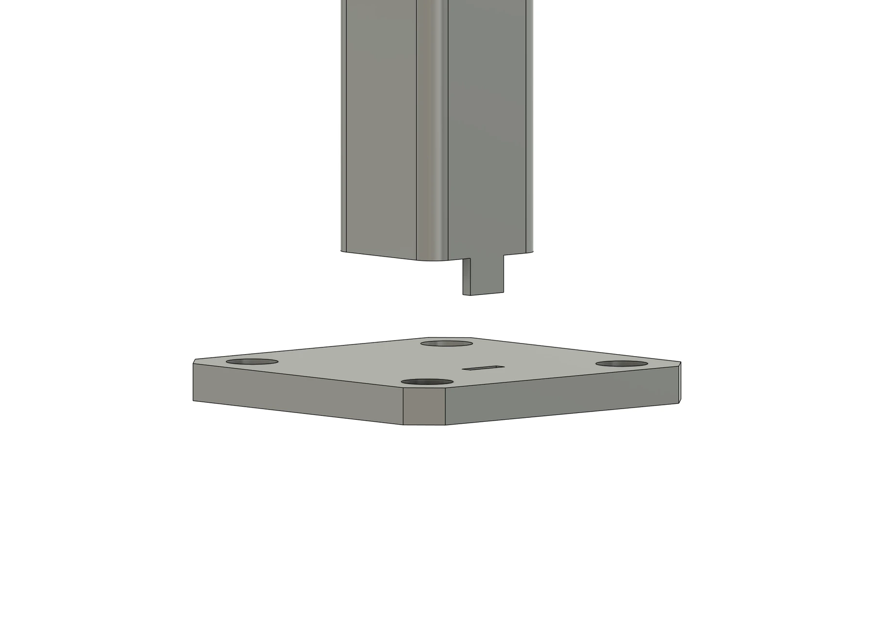
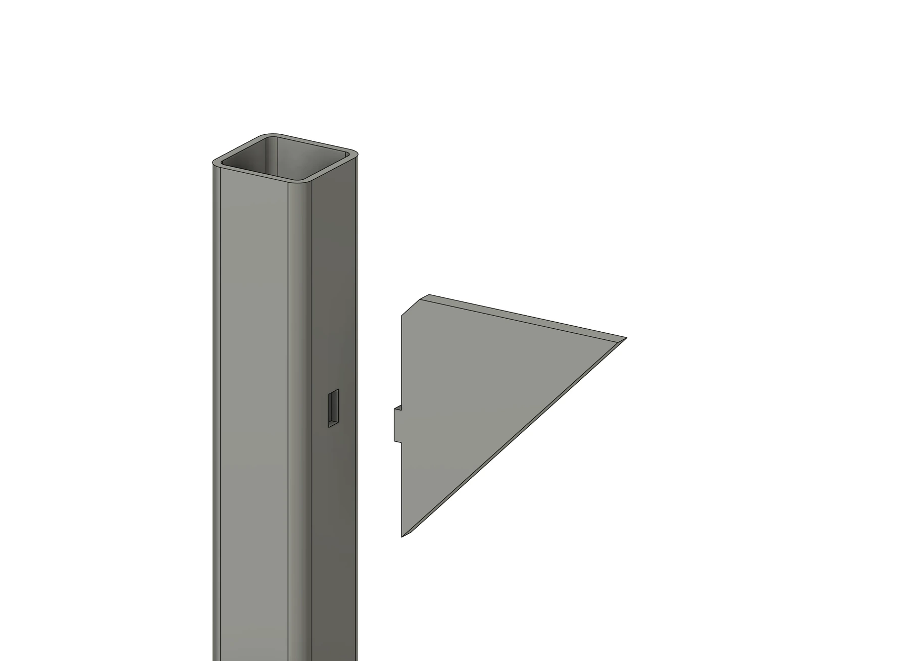
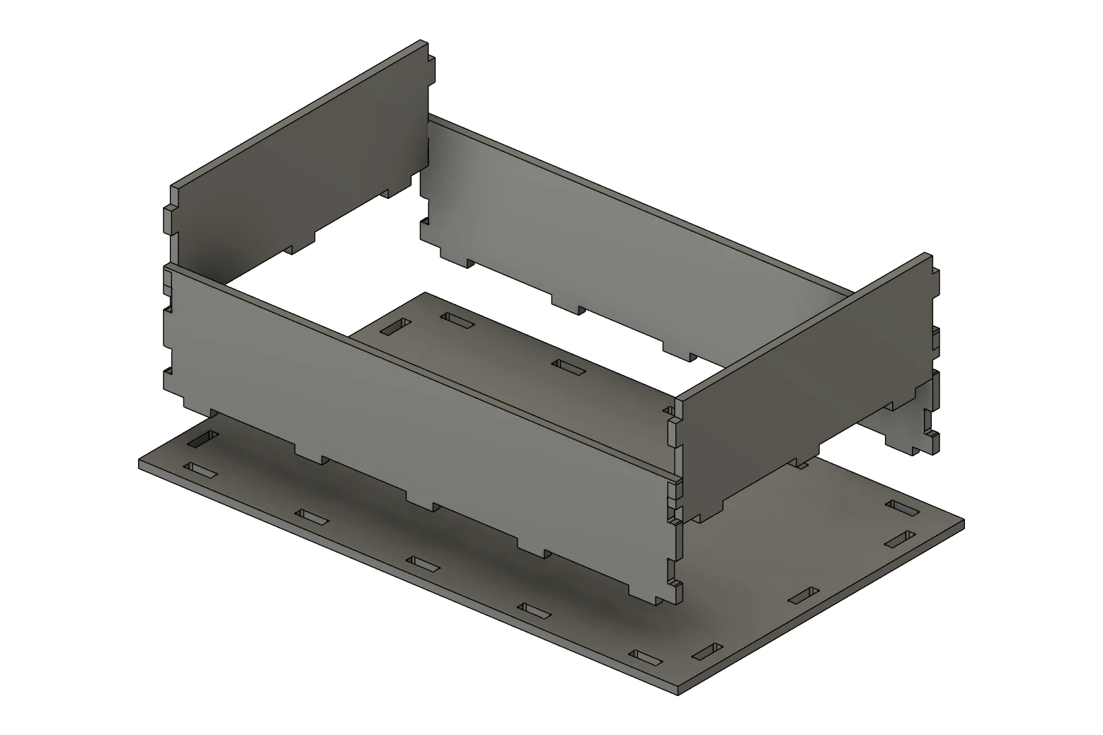
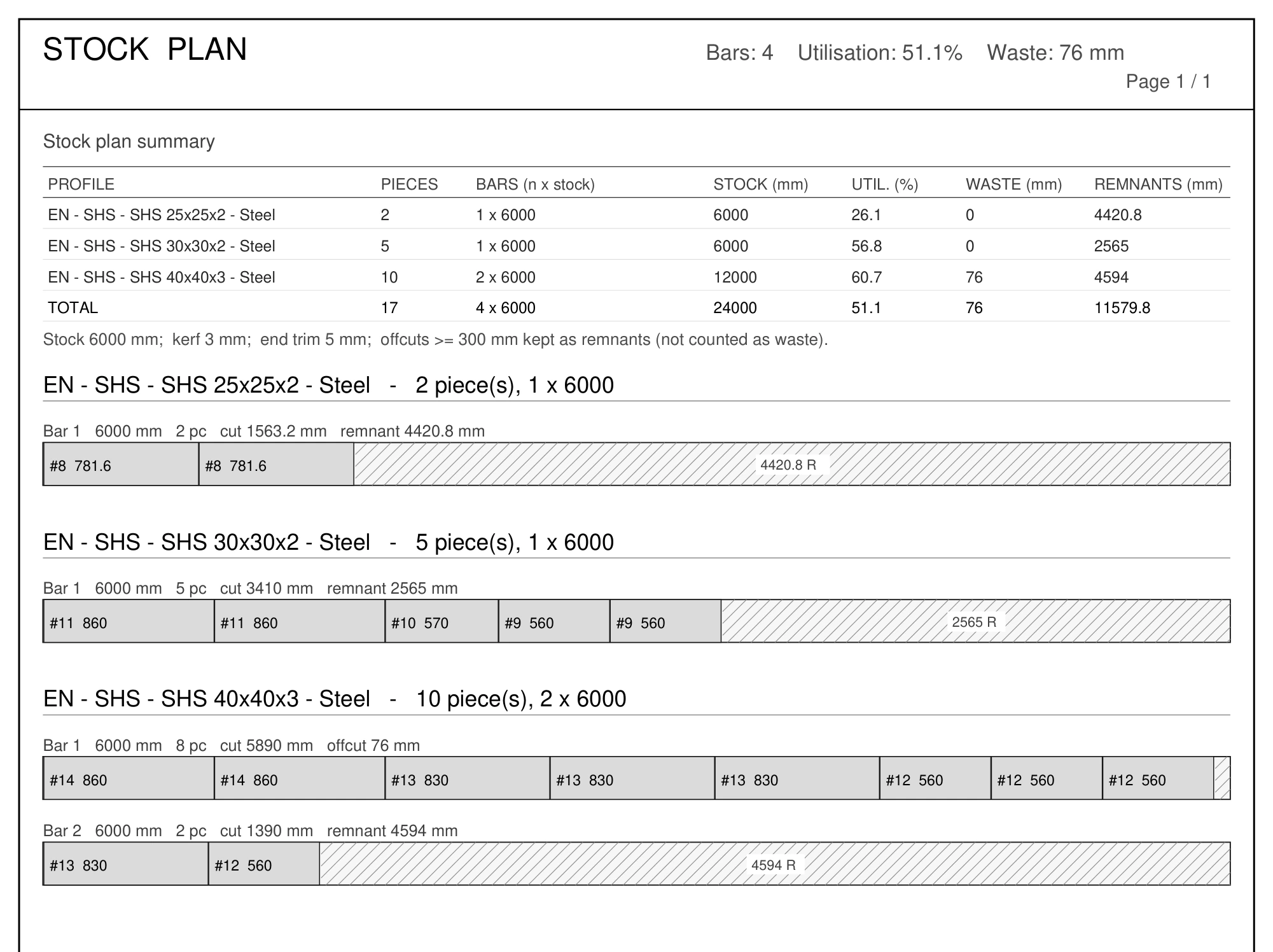
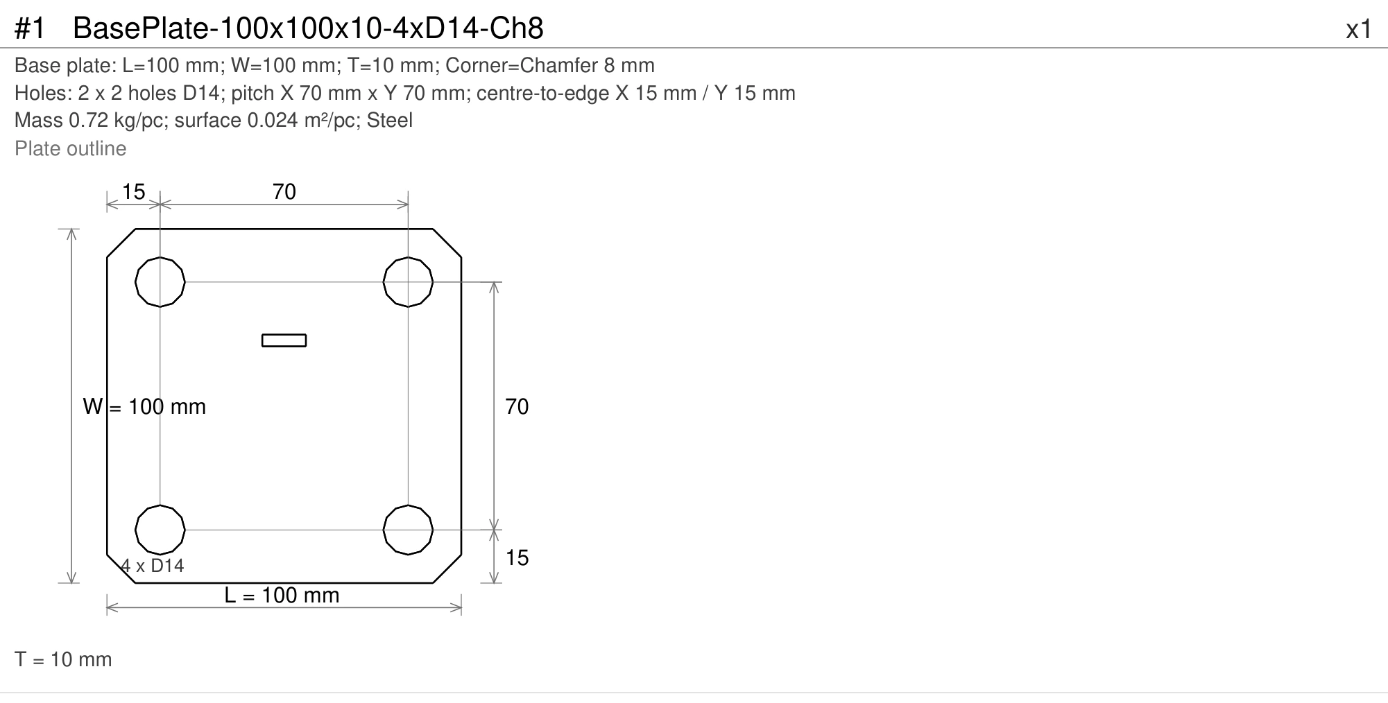
Base Plate and Weld Bead sit in the Create panel next to End Cap; Plate Tab / Slot and V-Notch & Fold are in the Modify panel; Stock Optimizer, Plates to DXF, Weld Cost, Frame Check and Frame Studies follow Cutting List in the Fabricate panel.
Make one tube from a connected run: multi-direction folds, tab/slot seams, per-corner settings and unfolded STEP or Fusion export.
Fillets and Square/V/Bevel grooves, automatic groove measurement and weld schedules. Smooth, Textured and Rippled finishes.
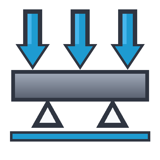
Inspect the model, calculate forces, stress and deflection, save load cases and design versions, export reports.
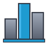
Show, compare and combine saved load cases, compare design versions and export the comparison to PDF or CSV.
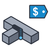
Consumable, arc and labour time, cost per weld with process presets.
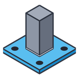
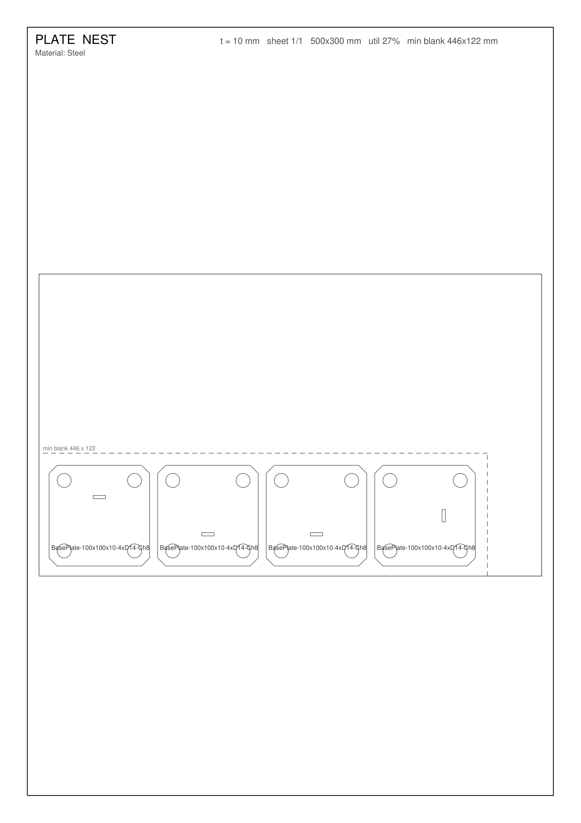
Foot and mounting plates with rectangular or PCD bolt patterns.
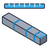
Cut list nested onto stock bars; bars to order, waste, cut plan.
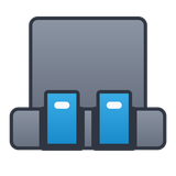
Rows of tabs and matching slots between any plates, including the ones you modelled yourself.
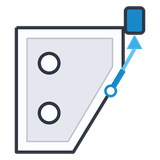
Flat DXF per plate type, your own plates included, with a quantity index and nesting onto stock sheets.
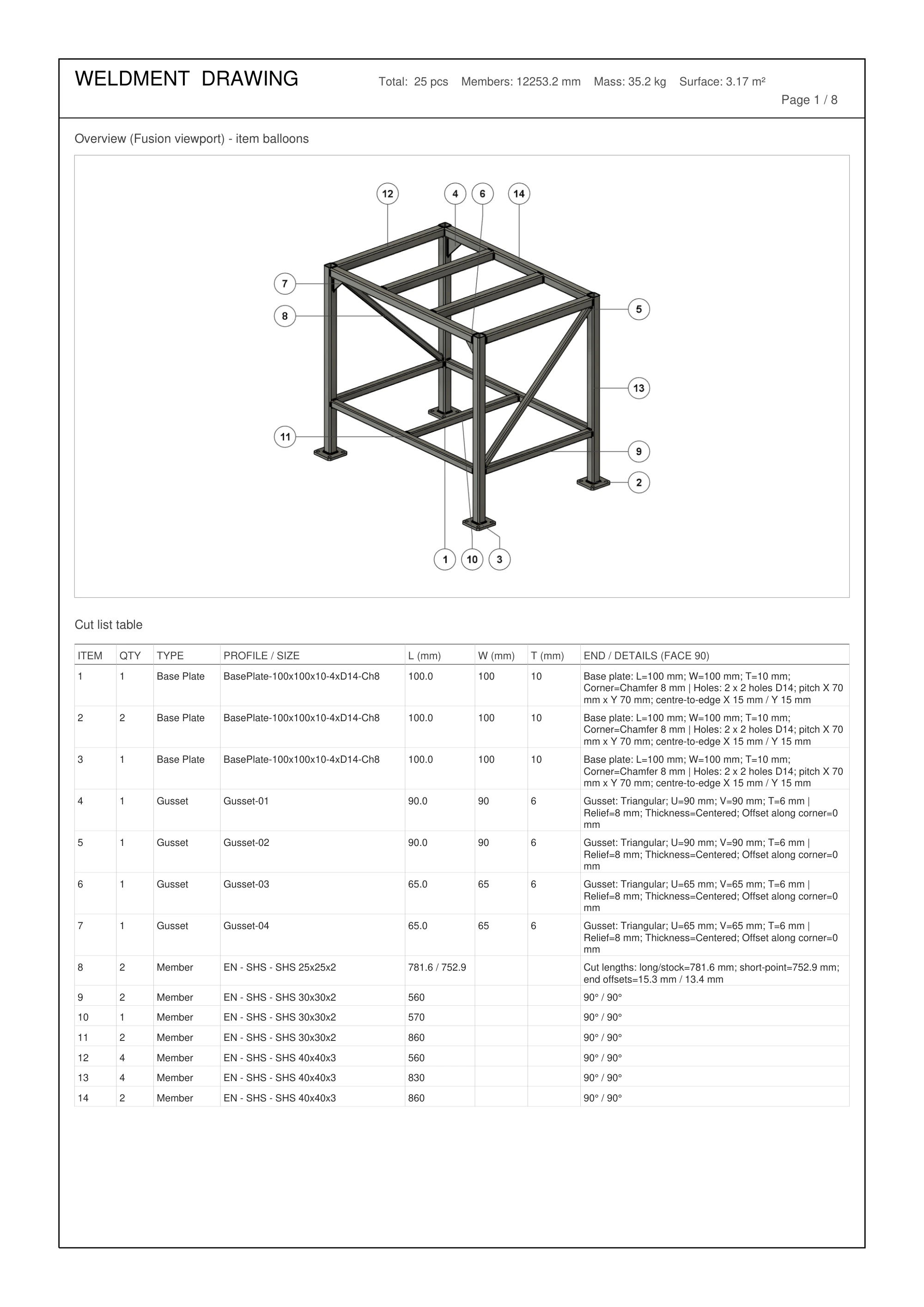
Weld schedule, stock plan pages, mass, surface, part descriptions, per-frame scope and coating cost — plates you modelled yourself included.
Real output samples
Inspect actual outputs from the Fusion sample frame before buying. See how parts, welds, bar plans and calculation assumptions are presented, and try the fabrication files in your own software. No sign-in is needed.
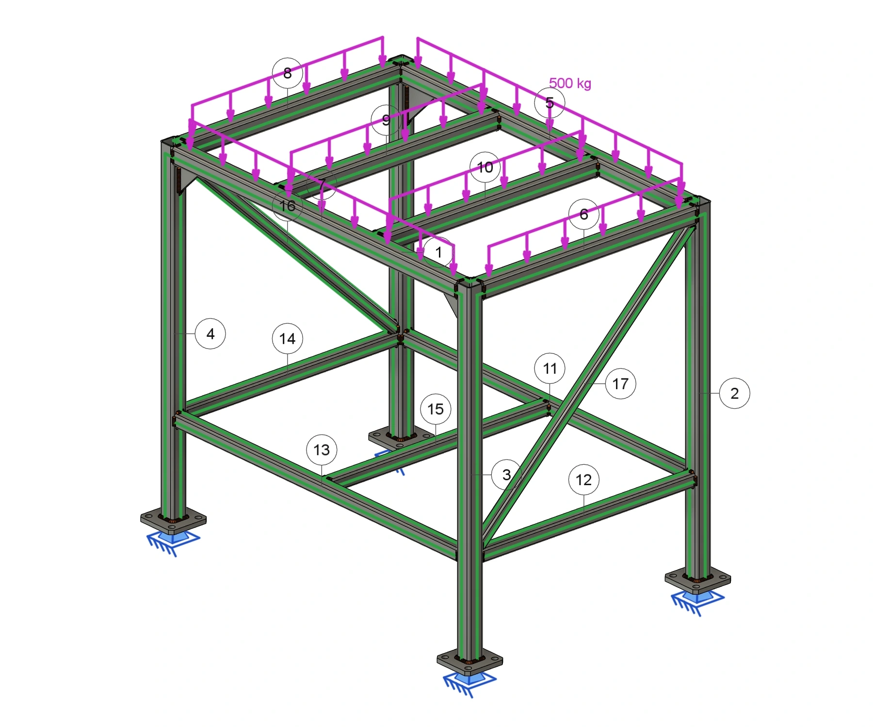
The downloadable report sample contains 25 parts: 17 members, four base plates and four gussets, with 42 weld groups. Its Frame Check case uses 500 kg distributed across six top rails, self-weight, Steel S235, four fixed feet and an L/250 deflection limit. These are the sample assumptions, ready to inspect in the report.
Eight pages: overview, numbered parts, cutting list, weld schedule and stock plans. Check the full-size tables and quantity notes.
Open fabrication PDF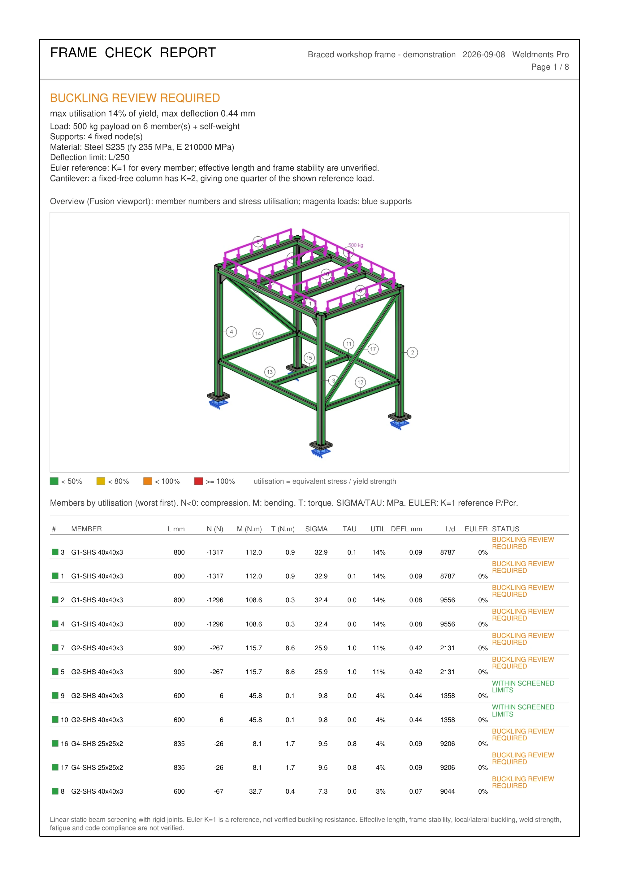
Eight pages documenting the load case, supports, member results and screening notes. The report records what was calculated.
Open Frame Check PDFSeven individual plate DXFs, a plate index, two nested-sheet DXFs and their layout PDF, plus stock and weld-cost CSVs. The package identifies its contents and units.
Download shop files ZIPNeed the workflow behind these outputs? Read the Pro user guide.
Standard or Pro
Quick pick: need V-Notch & Fold, weld beads, weld cost, Frame Check, base plates, a stock-bar cut plan or plate nesting? That is Pro. Just modelling frames, plates, cut lists and plate DXFs? Standard is the complete tool for that job.
| Capability | Standard | Pro |
|---|---|---|
| Price per user | US$49/yr or US$8/mo | US$89/yr or US$12/mo |
| Free trial | 3 days | 3 days, or 7 with an active Standard license |
| Frame, Member, miter / butt / cope, corner override, weld gap | Included | Included |
| Gusset, End Cap, Tab / Slot joints, Notch, Miter, Trim / Extend | Included | Included |
| Plate Tab / Slot: tabs and slots between any plates, including your own | Included | Included |
| 845 sizes in 43 families, including 229 Indian (IS) sizes: SHS, RHS, CHS, ISA, ISMC, ISMB, NPB and WPB; custom profiles and CSV import | Included | Included |
| Cutting List: table, CSV, PDF cut sheets with balloons | Included | Included |
| V-Notch & Fold: one tube, multi-direction folds, tab/slot and per-corner settings | — | Included |
| Unfolded tube STEP / Fusion export, developed lengths and notch tables | — | Included |
| Mass and surface area per piece (paint / galvanizing) | — | Included |
| Weld Bead: beads, weld schedule, textured / rippled options, on any bodies in the assembly | — | Included |
| Frame Check: member forces, beam stress / deflection and reports | — | Included |
| Frame Studies: compare load cases, combinations and design versions | — | Included |
| Weld Cost estimate | — | Included |
| Base Plate with bolt patterns | — | Included |
| Member-to-base-plate and gusset-to-member Tab/Slot | — | Included |
| Stock Optimizer (1D bar nesting) + stock plan pages | — | Included |
| Plates to DXF + index, including plates you modelled yourself | Included | Included |
| 2D plate nesting onto stock sheets (layout PDF + DXF per sheet) | — | Included |
| Weld symbols on the WELD LIST + weld tags on the overview | — | Included |
| Drawing-ready part descriptions (Parts List) | — | Included |
| AI control (MCP) of the add-in | Included | Included |
License
Pro costs US$12/month or US$89/year per user. App Store purchases unlock through Autodesk Entitlement when you sign in to Fusion. Activation codes are available for team installs and direct licensing.
Try Pro free for 3 days, or 7 days with an active Standard license, starting with your first use of Pro in Fusion. The longer trial uses your original start date, including trials already started. Downloading or reinstalling does not start or reset the trial.
Windows and macOS. Built for fabricators who quote, cut and weld what they model — machine frames, tables, guards, carts, trailers, structures.
The same add-in runs on Windows and macOS. Pick the machine you will install on.
Checking…
Adding the ZIP by hand? In Scripts and Add-Ins › +, select the folder that contains the .manifest file, not the file: on Windows, the Contents folder inside the .bundle.
Updating or switching versions? Clear Run on Startup for the old add-in, Stop it and close Fusion before replacing files. Restart Fusion before you Run the new version.
Yes. V-Notch & Fold in Weldments Pro turns a connected run of mitred Frame or Member parts into one folded part. Bends can turn in different planes. It retains the outside hinge wall and offers weld gaps, semicircular tabs and slots, and corner reliefs. All members must share section dimensions, wall thickness and material. Standard does not include this command.
Yes. Use Corner overrides for single bends and Edit Fold to change the saved run later; invalid folds are reported and must be fixed before fabrication export.
Export tubes writes the notched straight solid to STEP or a new Fusion design, and Cutting List counts the run as one part with its developed length and notch table. Existing holes, slots and end cuts on the members travel with the unfolded geometry.
Yes. Every release is published as a Windows bundle and a separate macOS bundle with identical commands. Pick your platform in the download section on this page; a licence covers both.
Use the schedule to estimate consumables and welding time. It combines measured seam lengths with section areas and estimating allowances. A ~ prefix marks approximate quantities, with the basis recorded in the export. Curved or unresolved sections can use local-section or nominal-section estimates. These values do not establish weld strength or a qualified welding procedure.
Supported joints produce solid beads. Some curved or oblique intervals remain counted-only when a reliable solid cannot be built; the schedule identifies the length without a bead. Smooth or Textured controls appearance; optional Rippled adds physical surface detail while retaining the same nominal schedule quantities. Version 2.4.0 improves supported rounded corners, oblique contacts and brace-to-rail seams. Review unusual joints in the seam preview before creating them.
Version 2.6.3 adds custom names for Frame groups and fixes gusset placement on profile-to-plate joints, including supports inside assemblies. It also fixes gussets and linear patterns disappearing after editing frame profiles. Recent releases added V-Notch & Fold with straight-tube export, 229 Indian Standard profile sizes, illustrated tooltips and improved end-member alignment in 3D frames. See the changelog for the changes in each version and Latest build for platform availability.
Use Weldments members for member-to-member and member-to-base-plate joints, or a planar constant-thickness Weldments gusset for gusset-to-member joints. Pick the tab body, then the receiving body. The command finds the contact and refuses ambiguous contacts, openings or insufficient material. For plates you modelled yourself or imported, use Plate Tab / Slot: it takes any solid bodies, in any component, and adds a row of tabs along every edge that rests flat on the receiving part.
Yes. With Scope set to Selected bodies, pick any solid bodies: Weldments parts or plates you modelled yourself, in any component. Parts inside moved, rotated or nested components are welded where they sit in the assembly. When a component is placed several times, pick the bodies of the instance to weld; each instance gets its own weld. Beads are created at the top level of the design, so run Weld Bead again if you move a part afterwards. Entire design keeps to the parts the add-in built.
Yes. Enter the bar lengths you buy, saw kerf, end trim and minimum reusable offcut. Weld Cost also lets you edit process efficiency, deposition rate, operating factor, labour, consumable and gas rates. Settings are remembered. Waste and cost depend on your job and these inputs.
It calculates member forces, moments, stress and deflection for an idealised linear-static 3D beam model using the loads, supports, sections and materials you choose. Compression requires a separate buckling review; it is not a design-code check.
It prints weld symbols on the WELD LIST pages and weld tags on the model overview of its fabrication PDF. It does not place weld symbols in a Fusion Drawing; use Fusion’s own drawing symbols there.
Frame Studies (Fabricate panel) works with the load cases you save in Frame Check. It shows any case on the current frame, compares all cases side by side, combines cases with your own signed factors (for example 1.35D + 1.5L) and compares saved design versions (Rev A, Rev B) for mass, peak utilisation and largest displacement. Comparisons export to PDF or CSV with support reactions, an equilibrium check and uplift. Factors are user-defined, not a design-code load combination, and the results use the same beam model as Frame Check.
Plate exports use R12 DXF in millimetres or inches with lines, circles and arcs, plus a CSV quantity index. Download the sample files and check them in your shop software. Flat plates you modelled yourself are exported and nested together with the add-in plates. Set material, thickness, spacing and stock sheet size for your job before exporting a nested layout.
Pro recognises frames and supported parts made by Standard. Open a copy of an existing project and try the Pro tools for 3 days, or 7 days with an active Standard license. Standard can open the model, but its license does not unlock Pro commands after the Pro trial ends.
Download Pro on this page with your Autodesk purchase email and run it with the same Autodesk account; the 7 days count from your first use of Pro.
No. Member descriptions are ordinary Fusion component properties. Enable the Description column in the Fusion drawing Parts List to show profile, length and end cuts, and use the normal drawing balloons.
Feedback
Most of Pro started as somebody describing a step they still did outside Fusion. Bugs, missing profiles, a report the shop wants — send it with the email your Fusion account uses.
Already sent feedback?
My Reports →Development roadmap
The planned work below has no confirmed release date.
Straight, end-to-end members with compatible mitres only. Curved members, round tubes, solid bars, I/H/T and custom sections are unsupported. Branches and disconnected selections cannot form one folded run.
Radius, gap, relief and tab limits depend on the section and space between bends. Bend allowance uses your K-factor; material springback and machine toolpaths are not simulated.
Read the fold workflow and parameter limits →Rebuild to apply the improvements
Rebuild beads created with older versions to use the improved seam detection, transitions and one-piece curved runs; existing beads change only when you run Weld Bead again. After moving a welded part or changing a groove, reselect the joint and rebuild it at its new position.
Extend the existing rounded-corner and oblique-seam support to freeform surfaces, narrow supports and complex multi-part corners, with checks for reliable bead geometry.
Build on straight and round/rectangular tube-perimeter Square/V/Bevel workflows: evaluate other curved paths and preparation tools, with support checks before expanding coverage.
Choose weld type and size per joint within one frame workflow, with the settings carried into the weld schedule and cost estimate.
Use member forces, stress and deflection to compare supported frame designs under the loads you enter. Read the results with the assumptions below; a green member is not a complete structural approval.
Evaluate more complex and extrusion outlines with a verified torsion model before adding them to the solver. Current support covers the recognised section families described above.
More for Autodesk Fusion (Fusion 360)
Frames, joints and cut lists
From tube routes to fabrication packages
 Sheet Metal & Press Brake
Bend sheets for the press brake, from the Fusion flat
 Hole Series & Fasteners
Matching holes and bolts in every part
 Auto Backup & Export
Local backups of your Fusion cloud designs