01
Sketch the centerlines
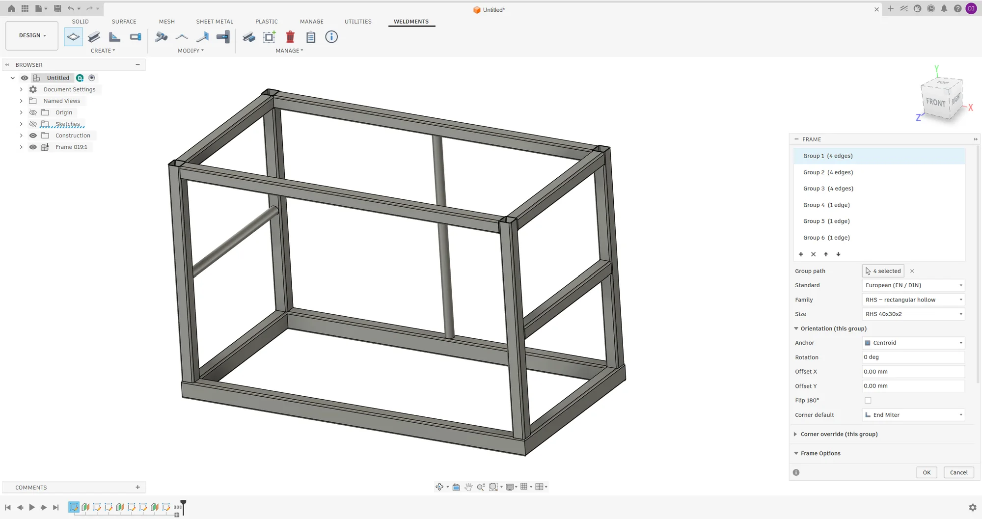
Draw lines, arcs, or use model edges. Select each structural role as a separate group so the priority and corner rules stay clear.
Build frames from sketches.Solve joints, tabs, plates,and export cut lists in Fusion 360.
Windows and macOS builds · free 3-day trial
Why it matters
Steel Frame & Weldments turns centerline sketches into structural members with repeatable trim rules. It is built for fabricators, fixture designers, machine frames, carts, benches, guards, 3D-printer and CNC frames, and any welded or bolted structure that needs both geometry and a usable cut list.
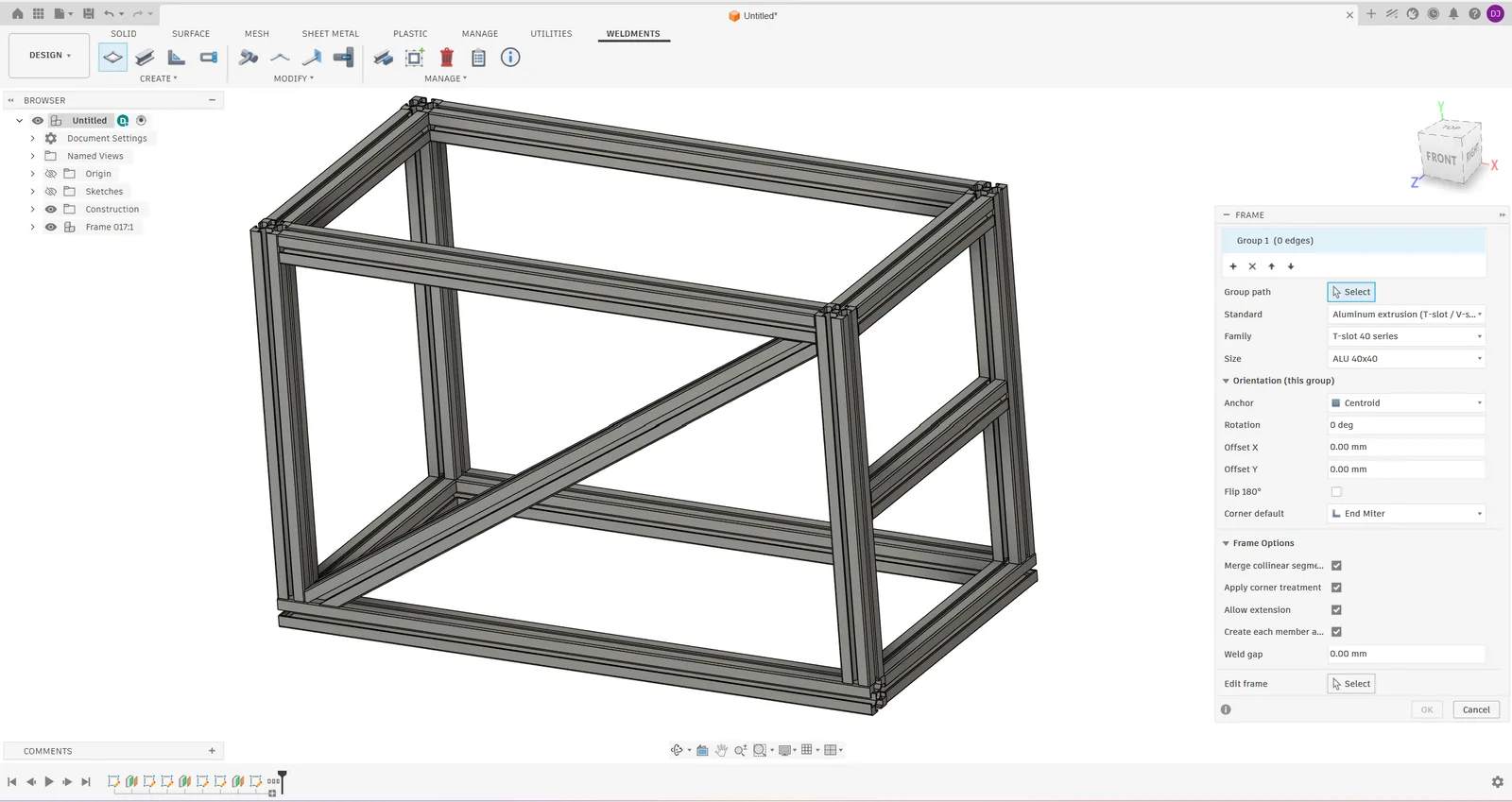
Select sketch lines, arcs, or model edges. Build several profile groups in one command, with predictable group priority, and reopen the frame later to rebuild it.
End miter, End Butt1, End Butt2, simple cut, coped cut, weld gap, X-cross cleanup, allow extension, and a per-corner override. Every build is verified: incomplete joints are reported, never hidden.
43 profile families covering EN/DIN, ANSI/AISC, JIS and Indian IS sections, plus real T-slot and V-slot aluminium extrusions. Add your own with CSV import or a closed sketch.
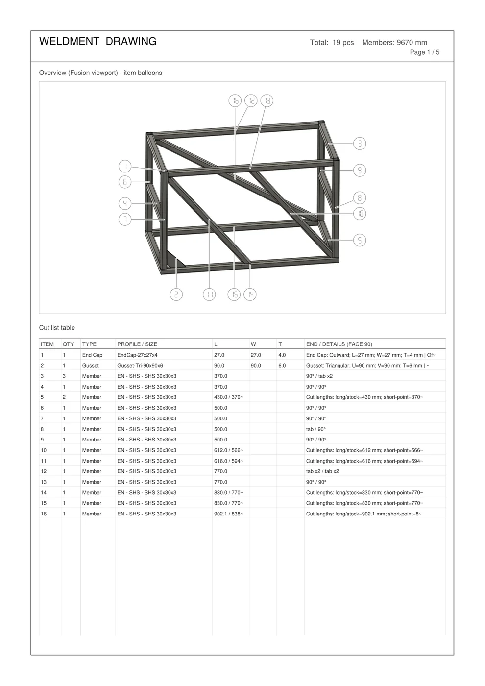
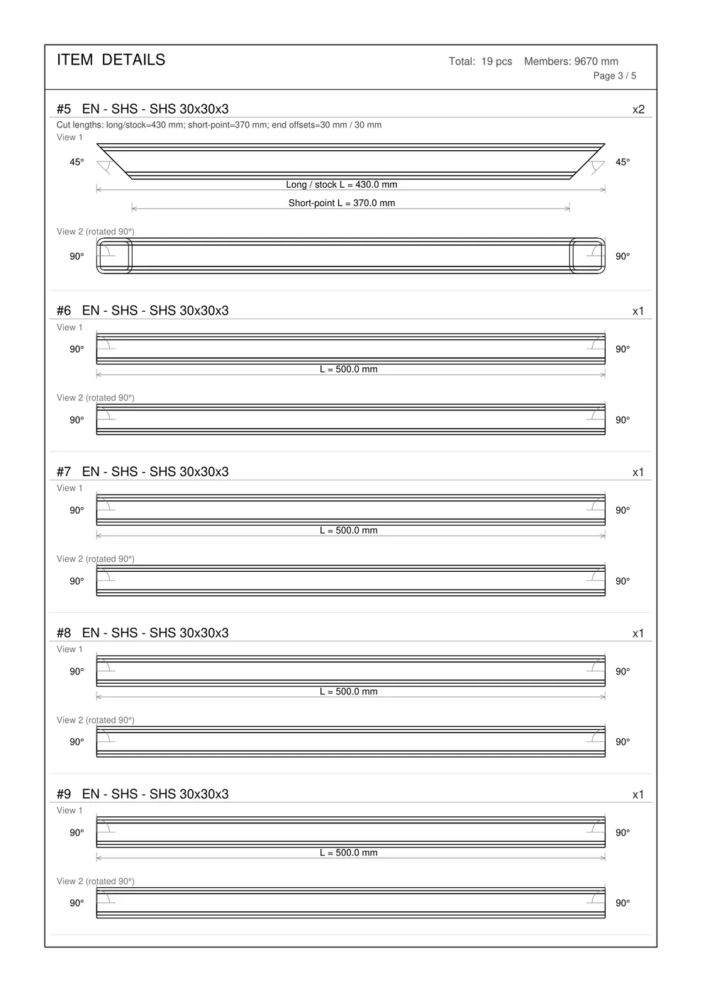
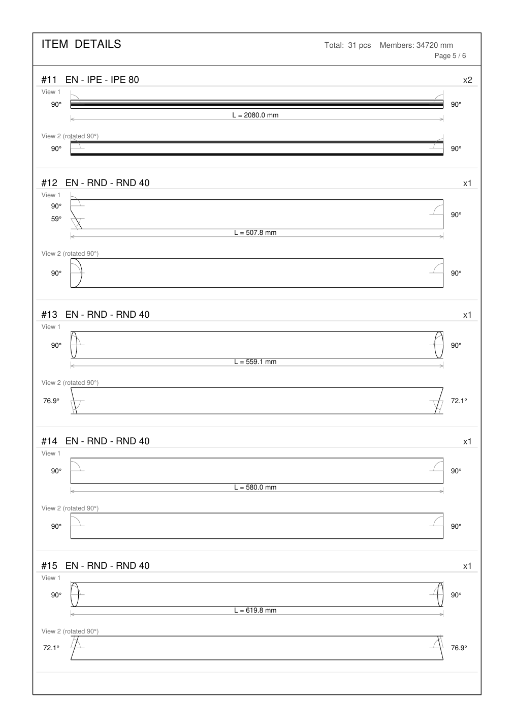
Export CSV plus printable cut sheets with lengths, long/short points, end angles, arc data, gusset dimensions, and end-cap outlines — in mm, cm, m, inches (1/16 fractions), or feet. Plates go to the laser as flat DXFs.
Switching CAD
The same jobs, done with Fusion commands. It is an add-in rather than a separate environment: members are ordinary Fusion bodies, or components if you choose, so drawings, joints and parts lists work with them as usual.
| In SolidWorks or Inventor | In Steel Frame & Weldments |
|---|---|
| Structural members / frame members on a sketch | Frame: several profile groups from sketch lines, arcs or model edges; Member for a single piece |
| Trim / extend, end treatments | Corner rules per group (miter, butt, coped cut), per-corner override, weld gap; Trim / Extend, Miter and Notch commands |
| Gussets and end caps | Gusset and End Cap commands, editable after the frame changes |
| Weldment cut list | Cutting List: CSV and PDF cut sheets with lengths, end angles and balloons |
| Profile library and custom profiles | 845 sizes in 43 families (EN/DIN, ANSI/AISC, JIS, Indian IS, aluminium extrusion), plus your own profiles from a sketch or CSV |
| Weld beads and weld tables | Weldments Pro: Weld Bead and the weld schedule |
What differs: a frame is rebuilt from its saved settings when you edit it, instead of living in a separate weldment feature tree, and the joint rules are set per group and per corner.
Steel Frame & Weldments Pro
Fold one tube. Use V-Notch & Fold for multi-direction bends, tab/slot seams and an unfolded STEP for fabrication.
Model the welds. Create Rippled beads with a Textured surface, build weld schedules and estimate welding costs.
Check the frame. Apply loads and supports to review member forces, stress and deflection with Frame Check.
Plus base plates, bar cut plans, plate nesting onto stock sheets and PDF reports for the shop.
Active Standard owners get a 7-day Pro trial. Annual upgrades charge only the price difference for the time left in your paid Standard term, with the same expiry date.
See it in action
Real sessions in Fusion 360: the frame generator and weldments overview, a steel frame with tab and slot joints through to the PDF cut sheet, an aluminium (aluminum) extrusion frame from the built-in T-slot profiles, and tabs and slots on plates you modelled yourself, exported as DXF for the laser.
Built for real frame decisions
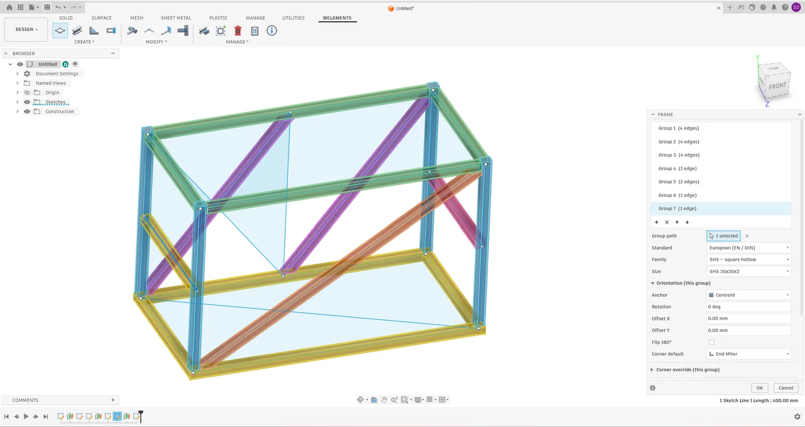
Put primary rails in Group 1, posts or secondary rails next, then braces, diagonals, arcs, and special profiles later. Earlier groups keep priority; later groups butt or cope to them — adding a brace never restyles a corner the main frame already owns.
Corner override
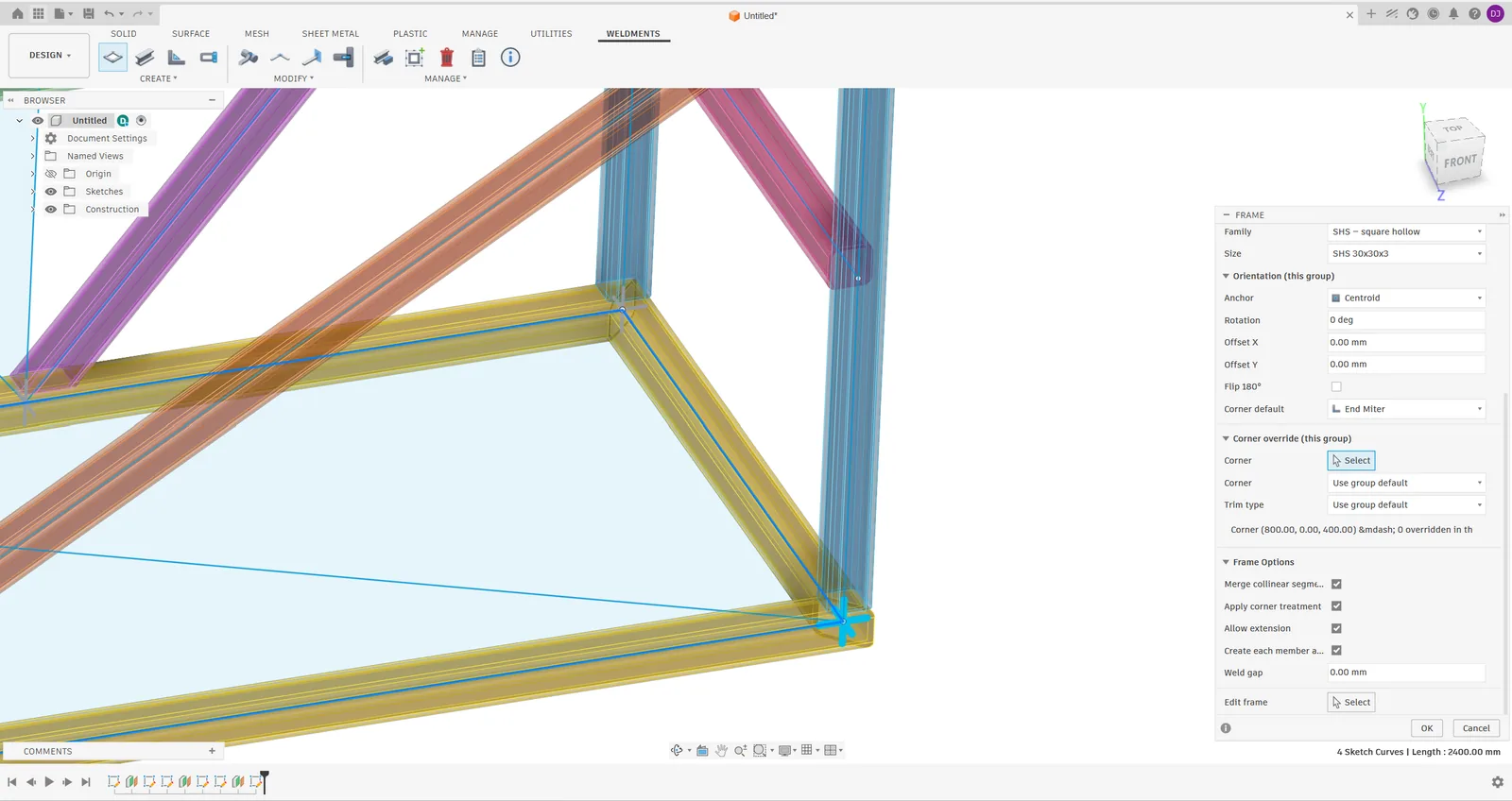
Group settings cover the whole group, which is usually what you want. When a single corner has to be different, you no longer have to split the group in two: expand Corner override, click a member near the corner, and give that corner its own style.
How it goes
Draw lines, arcs, or use model edges. Select each structural role as a separate group so the priority and corner rules stay clear.
The live preview uses BRep geometry, so coped cuts, hollow sections, arcs, and dense joints are shown before you commit. Add tab/slot joints, gussets, and end caps on the members you just built, and tab your own plates onto the frame.
Generate a model overview, item balloons, CSV, and PDF detail sheets for members, curved members, gussets, and end caps — in the unit your shop reads.
Select an existing Frame item and change groups, profile, section orientation, corner defaults, per-corner overrides, trim type, weld gap, or component mode. The frame is updated in place and keeps its component, name and timeline position.
Rebuilding a frame re-applies the tab/slot joints, gussets, and end caps recorded on it, scoped to that frame. Items you deleted by hand stay deleted, and anything that cannot be re-applied is reported instead of failing silently.
For large projects or controlled production drawings, create members as components and finish ballooning and drawing views in Fusion Drawing.
Laser-cut tube workflow
Pick the tab member, then the slot member. The add-in extends one wall of the tab member into a straight finger along its own axis — the only shape a tube laser can actually leave standing — and cuts the matching hole through the other member. Parts drop together in the right place, so the weld is the only thing left to do.
Tab and slot joints in the user guide →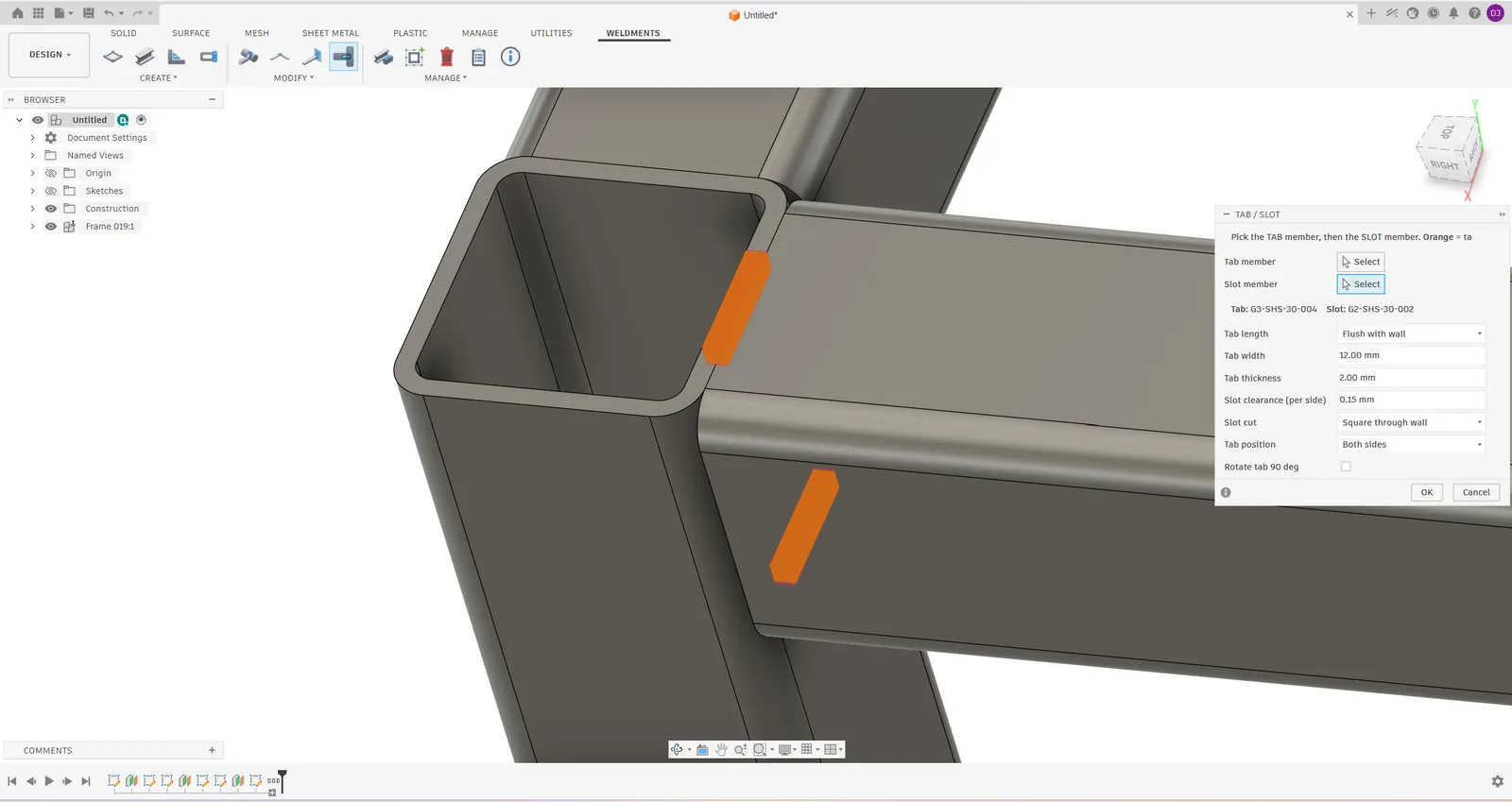
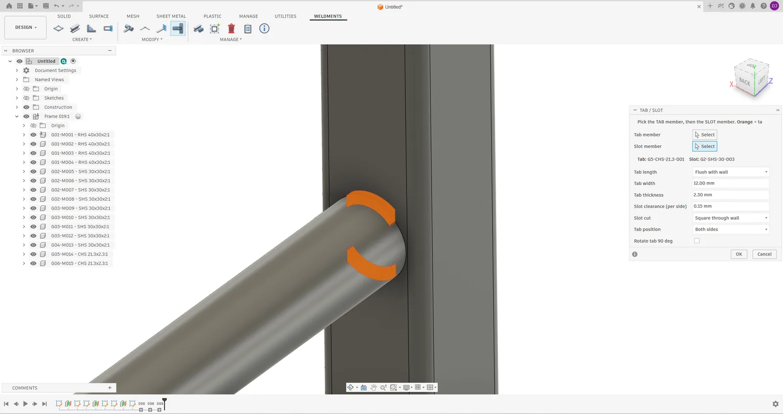
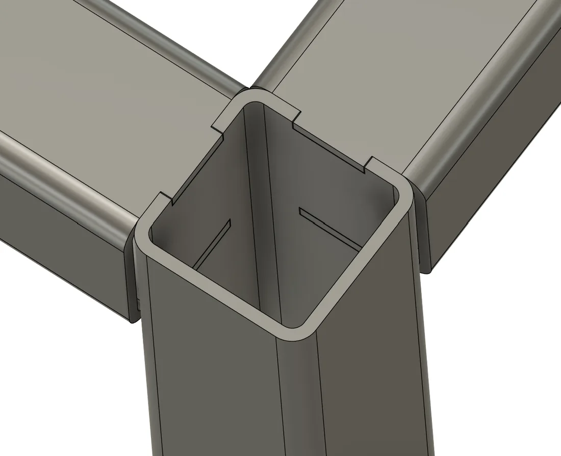
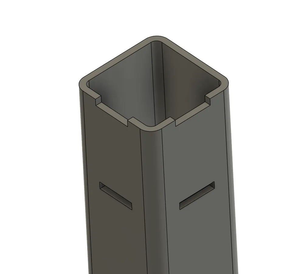
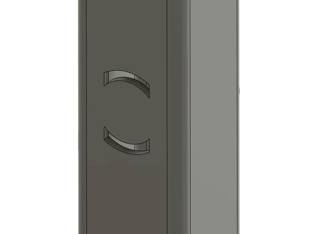
Square and rectangular tube, round tube, flat bar, angles, channels, and custom sections captured from a sketch. If the tab would aim at open air, the dialog says so before you commit.
A brace does not have to meet the wall at 90 degrees. The finger stays aligned with its own member, and the hole is elongated to receive it.
On round tube the tab is a curved strip of the wall, not a straight box hanging off the side. A near-square joint, and any joint cut with Angled with tab, gets a slot cut to the same curve; an inclined brace on the default square cut gets a straight-sided hole sized to clear it.
Square through wall works on any tube laser. Angled with tab follows the tab for a constant gap all round when you have a 5-axis or bevel head.
Place the tab automatically, on a chosen wall, on the centreline, or on both sides at once. Clearance is set per side, with 0.15 mm as the default.
Each joint is grouped in the timeline and recorded on the document, so rebuilding the frame re-applies it to the new bodies.
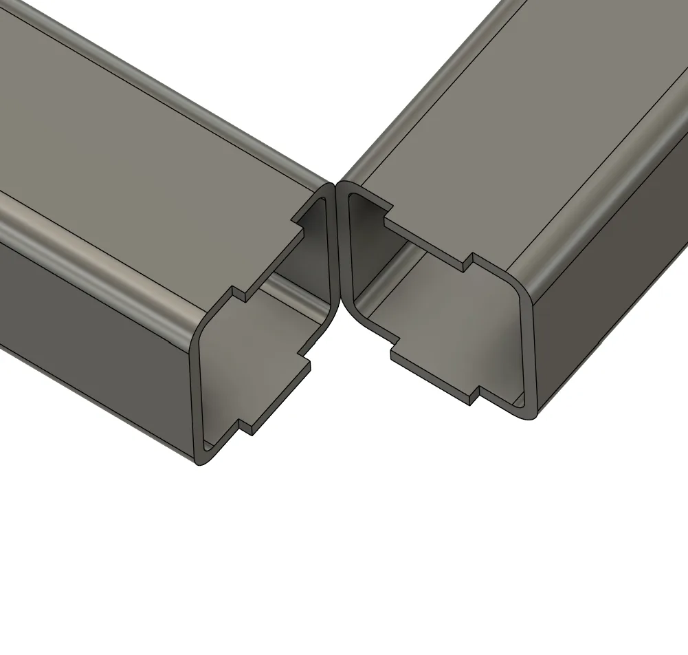
Plate fabrication
Plate Tab / Slot adds a row of self-fixturing tabs along a plate edge and cuts the matching slots in the part that edge sits on. It works on any solid body — plates you modelled by hand, imported bodies, gussets, end caps, and frame members as the slotted part — in the root or in any component of the assembly. Nothing has to be made by the add-in. Round parts work too: rings and holed plates around a tube, discs inside a tube, and tube ends standing on a plate.
Watch the Plate Tab / Slot and DXF walkthrough →Plate Tab / Slot in the user guide →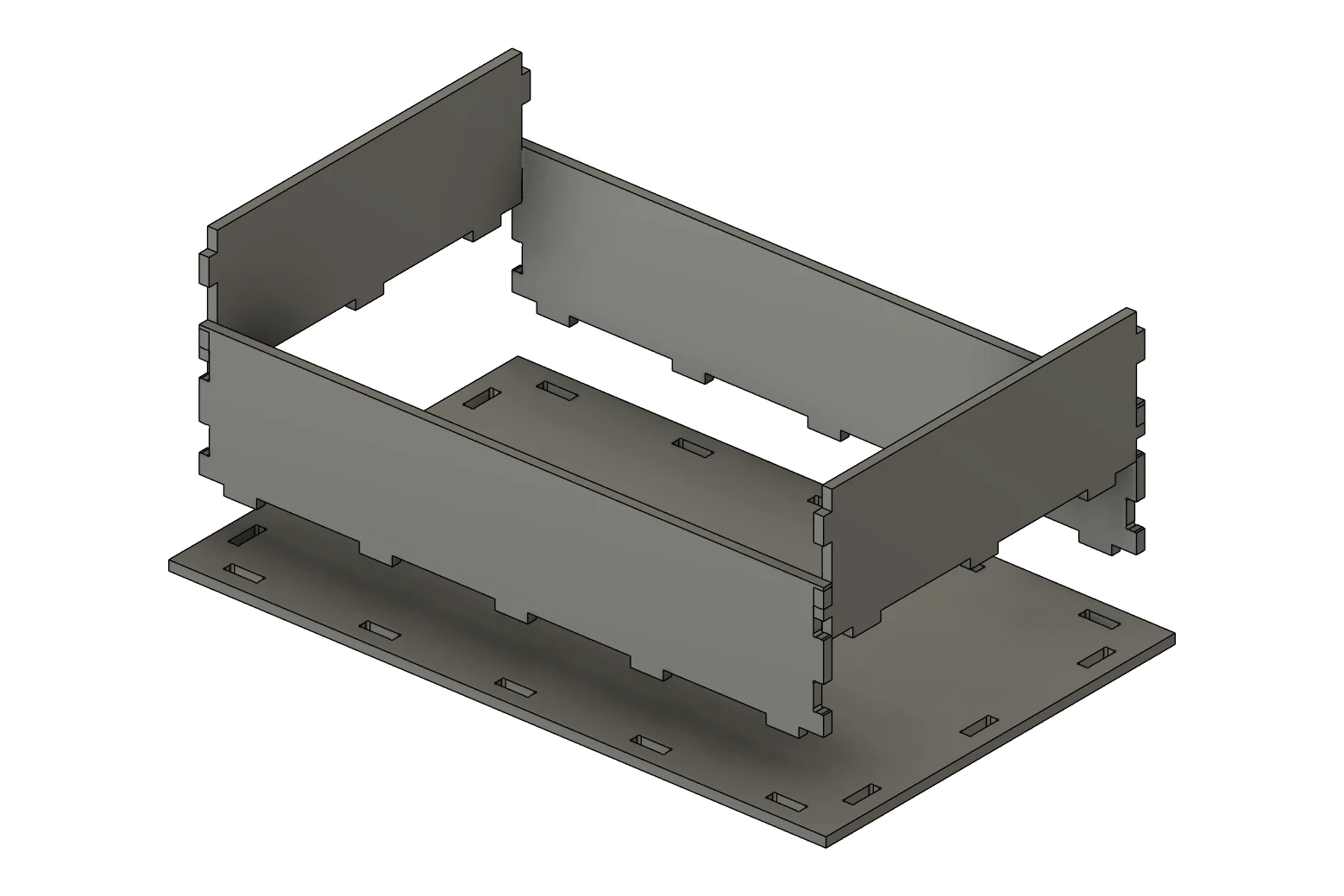
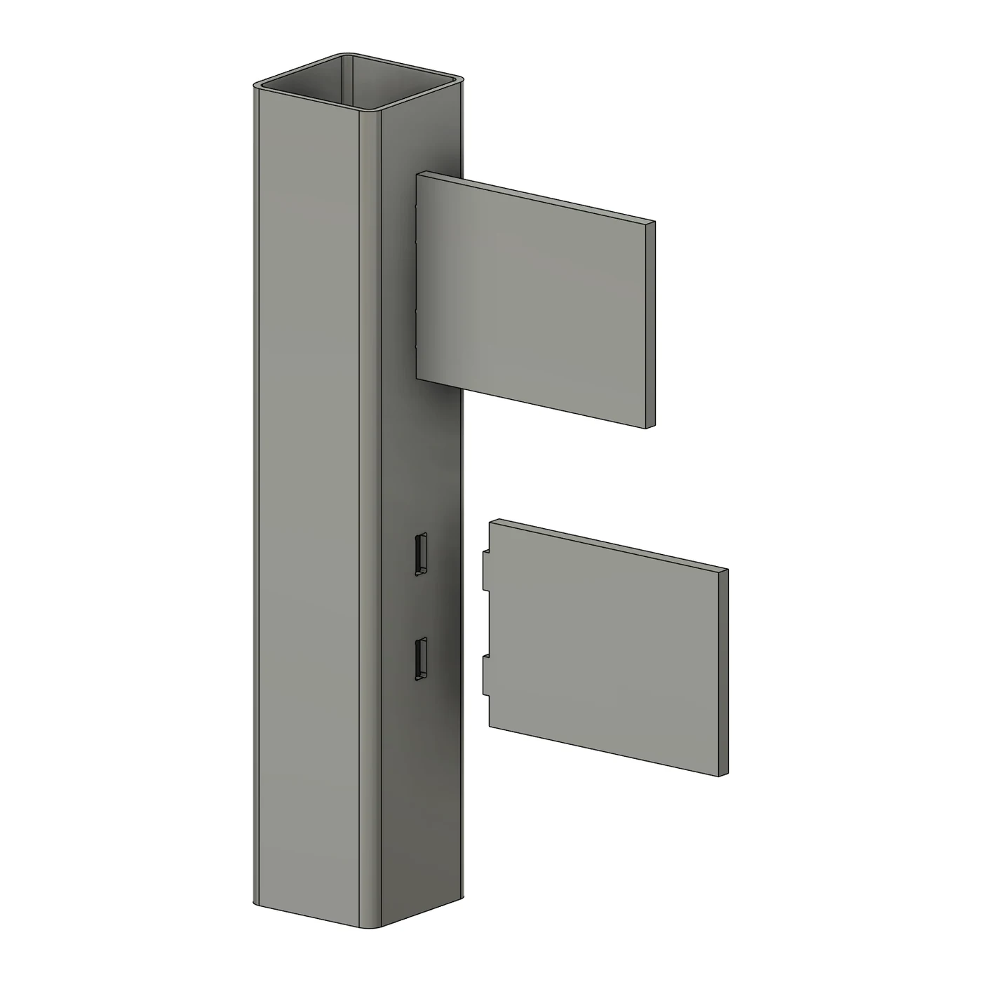
Hand-modelled or imported plates, gussets, end caps, and frame members as the slotted part. Bodies can sit in the root or in moved, rotated, or nested components.
Pick the tab plates, then the parts they sit on. Every edge resting flat on a slot part becomes a joint, so four walls and a base are one command.
The same number of tabs on every edge, or a maximum spacing so a long edge gets more tabs than a short one. Set tab width, end margin, and a flush or custom tab length.
Per-side fit clearance and optional round (dogbone) relief, so a sharp tab corner clears the radius a laser or plasma cut leaves. A weld gap of up to 2 mm is bridged by the tab.
A plate tabbed into a tube goes through the first wall and leaves the far wall untouched. Tabs that would land over a hole or past the supported edge are skipped, and the dialog says so.
Each joint is grouped in the timeline and recorded on the document. Editing a Frame, Member, Gusset, or End Cap re-applies it to the rebuilt part.
Plates to DXF
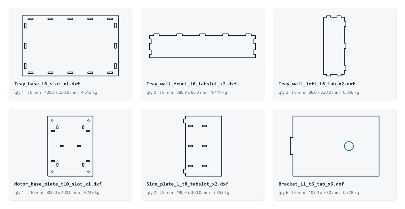
Plates to DXF writes one flat DXF per unique gusset and end cap — and per flat plate you modelled yourself — for the laser, plasma, or waterjet shop, with a plates_index.csv for the cutting order.
tab or slot in the name, so a tabbed gusset is never mistaken for a plain one.LABELS layer — or both.Nesting the plates onto stock sheets is part of Weldments Pro.
Profile library
845 sizes in 43 families covering EN/DIN, ANSI/AISC, JIS, Indian IS and aluminium extrusion. Steel sections include root and toe radii, tapered flanges where specified, and inside and outside corner radii on hollow sections. Aluminium extrusions are the actual extruded outline — slots, X core, and centre bore — so coped joints, notches, and end caps follow the real wall instead of a plain box.
In plain words: square and rectangular steel tube (SHS, RHS, HSS), round tube and pipe, I-beams and H-beams (IPE, HEA, HEB, W shapes), channel, angle iron, flat bar, and 2020 / 4040 T-slot and V-slot aluminum extrusion, including 80/20 series.
Capture any closed sketch profile, inner loops included, and reuse it in Frame or Member. Hollow custom sections stay hollow at coped joints.
Edit the parametric library as a spreadsheet, or hide the standards you never use so the dialog lists only what you buy.
Anchor, rotation, offset X/Y, and flip are set per group, so the same section can sit differently in different parts of the frame.
Included tools
Model the frame, add reinforcement, close open profile ends, then produce the fabrication package from the same tagged bodies.
Build multi-group frames from lines, arcs, and model edges. Reopen the saved frame and rebuild it after changes.
Create a single structural member when you do not need full frame grouping.

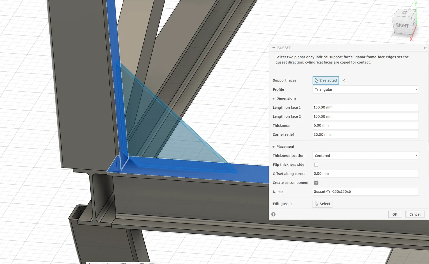
Add triangular or polygonal reinforcement plates between support faces, then edit dimensions and placement later.
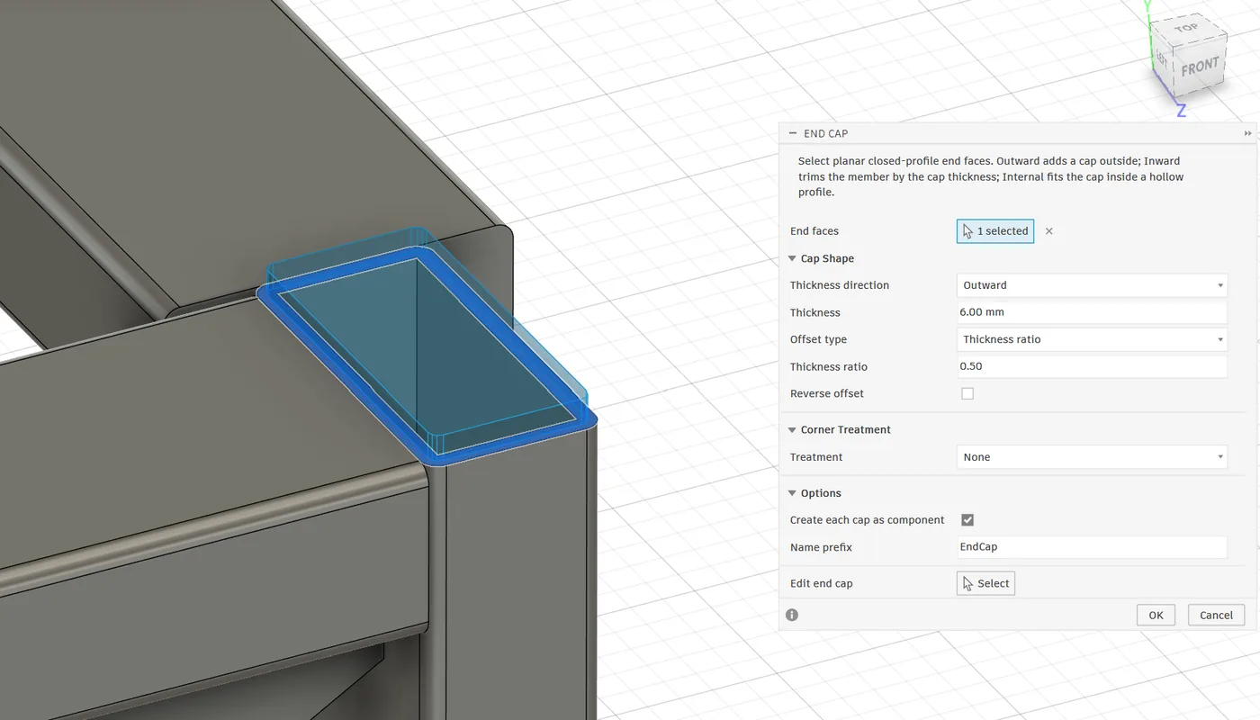
Close open profile ends with outward, inward, or internal cap placement. Edit thickness, offset, and corner treatment later.
Rows of tabs along plate edges and matching slots in the parts they sit on. Any solid body, including plates you modelled yourself.
Members, gussets, end caps and the plates you modelled yourself: CSV, model overview, item details and printable PDF cut sheets in the unit you pick.
One flat DXF per unique gusset, end cap, and plate you modelled yourself, plus a CSV index for the cutting order.
Show or hide standards, edit the naming patterns, and import or export the parametric library as CSV.
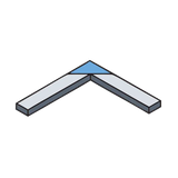
Finish two selected members with a controlled miter.
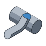
Cope a member by the body it touches.
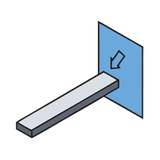
Trim or extend a member to a face or plane. Between Member-built members the end follows the target when a parameter changes; Fit to target member closes skew corners.
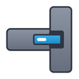
Add a self-fixturing tab on one member and a matching through-wall slot on the other, so laser-cut parts locate themselves for welding.
Capture a custom closed sketch profile.
Fabrication output
AI control
Weldments ships a local Model Context Protocol server, so an approved AI client can inspect the open design and build editable items in it. Everything it creates is an ordinary add-in item you can reopen and edit by hand.
License
A free 3-day trial starts automatically the first time you run the add-in (internet required). Subscribe on the Autodesk App Store — US$8/month or US$49/year per user — and the add-in unlocks through Autodesk Entitlement when you sign in to Fusion. Activation codes are also supported for manual grants, team installs, or direct licensing.
For Autodesk Fusion 360 on Windows and macOS. Built for designers who need faster frame modeling and cleaner fabrication data.
Not built in, as of September 2026: Fusion has no weldments environment and no Inventor-style Frame Generator. You can sweep sketch profiles by hand, or use an add-in. Steel Frame & Weldments places structural members along sketch lines, trims the joints (miter, butt, cope), adds gussets, end caps and tab and slot joints, and exports a cut list with lengths and end angles.
Yes. Every release is published as a Windows bundle and a separate macOS bundle, with the same commands and the same profile library. Buy once on the Autodesk App Store and use either; the download section on this page lets you pick the platform.
Yes. T-slot, V-slot, C-Beam and 80/20 extrusions ship as their real extruded outline, so joints and end caps follow the true wall.
Yes. Profile from Sketch turns a closed sketch into a reusable section, and CSV import adds your own sizes to the library.
Yes. Frame, Gusset, and End Cap store add-in data: select the created item in the matching dialog, change the settings, and OK rebuilds it. Edit Frame updates the frame in place, so its component, name and timeline position stay. Tab/Slot joints are recorded on the document too and replay automatically when the frame is rebuilt; to change one, delete its timeline group and place it again.
They follow it: rebuilding the frame re-applies the tab/slot joints, gussets and end caps recorded on it (details under How it goes, above).
Yes. Plate Tab / Slot works on any solid body, including plates you modelled by hand or imported, in the root or in any component.
Yes. Plates to DXF writes one flat R12 DXF per unique gusset, end cap, and flat plate you modelled yourself, in millimetres or inches, plus a CSV index with quantity, thickness, size, and mass.
Yes. Corner override gives one corner its own corner and trim type without splitting the group.
The preview runs the same BRep treatment as the final build.
Yes. Enable component mode for Frame members, and create gussets/end caps as components.
Yes. A 3-day trial starts automatically the first time you run the add-in in Fusion. All tools stay available during the trial; an internet connection is required to activate it.
Every Frame build is verified: if two members still overlap after treatment, the add-in names the joint that needs attention.
Download
App Store reviews take a week or more. Licensed users can download the latest build here with the email of their Autodesk account, or from inside the add-in (Info › Download latest version). The add-in still checks your license through Autodesk when it starts, so the file is only useful with a license.
After downloading, follow our installation and update guide for the ZIP bundle, switching from an older version, or uninstalling.
Not a customer yet? Buy on the Autodesk App Store.
The same add-in runs on Windows and macOS. Pick the machine you will install on.
Checking…
Adding the ZIP by hand? In Scripts and Add-Ins › +, select the folder that contains the .manifest file, not the file: on Windows, the Contents folder inside the .bundle.
Updating or switching versions? Clear Run on Startup for the old add-in, Stop it and close Fusion before replacing files. Restart Fusion before you Run the new version.
Feedback
This add-in is built and maintained by one person, and most of what is in it started as somebody’s report. Tell me what broke or what you need — no sign-up and no password, just the email your Fusion account uses so I know who I am replying to.
Already sent feedback?
My Reports →More for Autodesk Fusion (Fusion 360)
 Steel Frame & Weldments Pro
Tube folding, welds and frame analysis in Fusion
From tube routes to fabrication packages
 Sheet Metal & Press Brake
Bend sheets for the press brake, from the Fusion flat
 Hole Series & Fasteners
Matching holes and bolts in every part
 Auto Backup & Export
Local backups of your Fusion cloud designs